


Theoretical Background
The general method according to 5.8.6 has the following additional requirements with regard to analysis and design.
![]() Geometric Nonlinearity – Second-Order Analysis
Geometric Nonlinearity – Second-Order Analysis
According to Section 5.8.6(1), geometric nonlinearities must be taken into account. Accordingly, the internal forces are determined on the deformed system according to the second-order analysis, taking imperfections into account.
![]() Physical Nonlinearity – Material
Physical Nonlinearity – Material
The general rules for nonlinear methods according to 5.7 still apply. In Sec. 5.7(1), "an adequate non-linear behavior for materials is assumed". According to 5.7(4)P, the use of material characteristics that represent the stiffness in a realistic way, but take into account the uncertainties of failure, shall be used when using nonlinear analysis.
Thus, it is necessary to use the appropriate stress-strain diagrams for concrete and reinforcing steel.
- Creep deformation
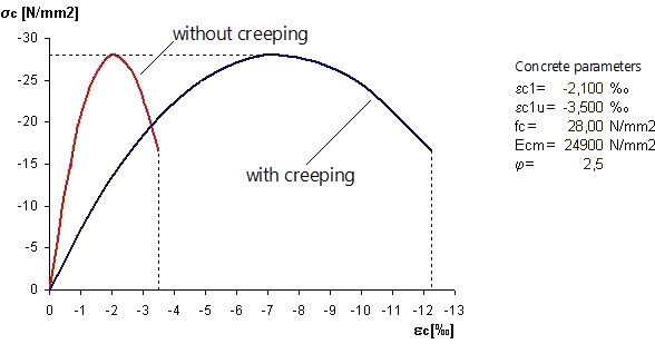
Creep must be taken into account and may be applied using a modified stress-strain diagram according to 5.8.6 (3). For this, the strain values of the concrete are multiplied by the factor (1 + ϕef), where ϕef is the effective creep ratio according to 5.8.4. The procedure is shown as an example in the following image.
- Tension stiffening
The effect of the concrete between the cracks (tension stiffening) may be taken into account. A suitable method must be selected for this, either using an appropriate concrete characteristic line for the tension area (1 in the image below) or using a modified reinforcing steel characteristic line (2 in the image below).

![]() Safety Concept
Safety Concept
- Internal forces and deformations
According to EN 1992-1-1, Section 5.8.6 (NDP 5.8.6(3)), the internal forces and deformations may be determined by using average material properties (fcm, fctm, …).
- Cross-section design in ULS
However, the design of the ultimate load-bearing capacity in the governing sections must be carried out with the design values (fcd, fyd, …) of the building material parameters.
Subject of Analysis
The modeling of the column to be analyzed is based on the Evaluation Example 0033-D-DBV-AK from [1] and Example 10 from [2]. It is located on the edge of a three-span frame structure consisting of four cantilevered columns and three single beams with a hinged connection.
For the design, the column is modeled as a single column. It is subjected to the vertical force of the precast girder, as well as snow and wind.
![Sketch of the structural system with individual supports marked | Excerpt from [2]](/en/webimage/054837/4364907/Gegenstand-der-Analyse_2025-02-04_EN.png?mw=760&hash=9a3792b2521056b32b7a575b85048cf7855c67d1)
Nonlinear Stability Analysis in RFEM 6
Based on the general principles, the nonlinear analysis and the ultimate limit state design are now carried out for the example mentioned above.
The Concrete Design and Nonlinear Material Behavior add-on are required.
Materials
First, class C30/37 concrete and class B500S(B) reinforcing steel are imported from the Material Library.
![]() Concrete
Concrete
For the "Concrete" material type, the "Anisotropic | Damage” nonlinear material model is very well suited for the design according to the general method.
Stress-Strain Diagram
In the "Anisotropic | Damage” tab of the material model, you can select various types of diagram definitions in the “General” category, including “ULS P+T | Design values acc. to 5.8.6". For this option, the safety factors that result from the standard selected in the Base Data for the concrete design are also specified below.
In the lower part of the dialog box, in the "Strengths" category, you can control the course of the diagram for the compression area and tension area using the strength parameters.
For the nonlinear analysis of the column, the compression area is represented by the "Parabola" diagram type (according to 3.1.5) and the compressive strength fcm, and the tension area by fctm.
It is also possible to activate the consideration of tension stiffening by applying suitable concrete characteristic lines for the tension area.
The "Stress-Strain Diagram" tab shows the resulting diagram on which the nonlinear analysis is based.
The following image shows the input dialog box for concrete of the “Anisotropic | Damage” material type.

Creep
You can activate creep in the "Time-Dependent Properties of Concrete" tab.
![]() Reinforcing Steel
Reinforcing Steel
For the “Reinforcing Steel” material type, select the appropriate nonlinear material model “Isotropic | Plastic”.
Stress-Strain Diagram
You can also set the diagram type for the reinforcing steel in the specific tab. In this example, the default setting is used.
The following image includes the input dialog box for reinforcing steel of the “Isotropic | Plastic” material type.

Structural System and Loading
The modeled structural system and its loading correspond to the specifications from [1] and are summarized in the following image.

Cross-Section – Advanced Time-Dependent Properties
If creep is activated in the Material dialog box, the "Advanced time-dependent properties of concrete" option is available in the dialog box for defining cross-sections.
The creep parameters used in this example are shown in the image below.

Member – Design Properties
The design properties for the column are activated in the member dialog box. The reinforcement is defined according to the reference solution [1] and summarized in the following image.

Imperfections
The imperfections are determined according to the specifications of Eurocode 2. In the example to be analyzed, the inclination ("initial sway") is θi = 1/315.

Mesh Settings
In the specifications for the generation of the FE mesh in the Mesh Settings dialog box, the option for the member divisions should be active for the nonlinear analysis of concrete members, as highlighted in the following image.

Analysis
The nonlinear analysis according to the general method in compliance with EC 2, 5.8.6, applies the settings as highlighted in the image below.

1 – Analysis Type for Linear Creep
In this example, the creep is modeled linearly using a modified stress-strain diagram (see the Creep Deformation section). For this, set the analysis type to "Static Analysis | Creep & Shrinkage (Linear)”.
2 – Creep Loading Times
The loading times for creep are defined in the "Times" section.
3 – Second-Order Analysis
The required second-order analysis for load combinations is already preset by default in the static analysis settings.
4 – Considering Imperfection
It is necessary to activate the imperfection to be considered for the corresponding combinations. You can assign it in the imperfection case, in the combination wizard, or in the load combination. Further information can be found in the technical article "Considering Member Imperfections" and in Chapter Imperfection Cases of the RFEM 6 online manual.
5 – Activating Reinforcement in Structure Modification
In order to consider the reinforcement stiffness in the finite element analysis, it is necessary to activate the member reinforcement using the structure modification for reinforced concrete, as shown below.

6 – Creep-Inducing Load
The corresponding quasi-permanent load combination should be used as the creep-inducing load level. The governing combination is set in the “Creep caused by permanent load from” option.
Settings for Concrete Design
For concrete design, the relevant design situation, the objects to be designed, and their ultimate configurations are assigned.
Further information on entering data for concrete design can be found in Chapter Concrete Design Settings of the introductory example for concrete design.

The results of the material and physical nonlinear analysis are transferred directly to the concrete design.
The settings for the concrete design can be found in detail in the RFEM file, which is available to download below this article.
Calculation and Results
Once you start the calculation, the nonlinear analysis is carried out, followed by the concrete design. Finally, the results are provided for the evaluation.
Structural Analysis
The following images show the results of the nonlinear analysis according to the general method in compliance with EC 2, 5.8.6.
The design moment distribution and the deformations are as follows.

The next image shows the deformation diagram depending on the load factor in the calculation diagram for the governing combination CO103, considering creep for the permanent load level. For comparison, the deformations of CO102 without the creep component are also displayed.

Concrete Design
The concrete design checks for the ultimate limit state, including the stability analysis according to the General Method in compliance with EC 2, 5.8.6, have been carried out.
The next image shows an extract from the design results.

Conclusion
In this technical article, the design according to the General Design Method of Eurocode 2, 5.8.6 was performed using an example of a reinforced concrete column.
In summary, the procedure can be divided into the following steps.
- Definition of the material with appropriate material models, stress-strain diagrams, and creep activation
- Creating the cross-section and defining creep parameters
- Modeling the structural system, including design properties
- Definition of loading with imperfections
- Check of the mesh settings
- Nonlinear analysis settings
- Analysis type (here: "Static Analysis | Creep & Shrinkage (Linear)")
- Second-order analysis
- Loading times for creep
- Activating reinforcement
- Running the analysis and design
- Result evaluation