2026-09-17
064975
Tension Stiffening | Activation Factor: Capacity, Angle, and Position
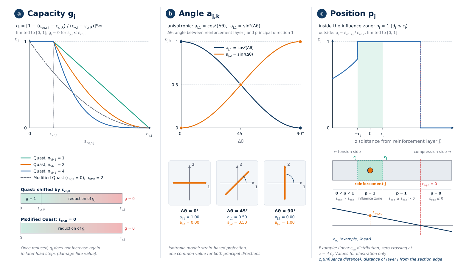
Diagrams of the three subfactors of the activation factor—capacity, angle, and position—of the local anisotropic tension stiffening extension
Three-part graphic showing the multiplicative partial factors of the activation factor Δα_j,k. Part a shows the capacity factor g_j as a function of the equivalent strain of the reinforcement: It remains at 1 up to the crack strain and then drops to 0 up to the yield strain; the distribution depends on the exponent n_VMB; in the modified Quast method, the displacement due to the crack strain is omitted. Part b shows the angle factor a_j,k as cos² (principal direction 1) and sin² (principal direction 2) as a function of the angle between the reinforcement direction and principal direction 1, with three sketches for 0, 45, and 90 degrees. Part c shows the position factor p_j: fully effective within the influence zone on both sides of the reinforcement (influence distance c_j); outside this zone, it depends on the ratio of the equivalent strains at the reinforcement and in the concrete layer, displayed for an exemplary linear strain diagram with cross-sectional strips.