.svg?mw=64&hash=343d71fbdf234f1411db2920f2dff33c0dbd6231)

Lattice tower | Rectangular plan | Rhombus diagonals (not interconnected, straight)
TSR038-a | Lattice Tower
| Block parameters editable dynamically | |
| Number of Nodes | 32 |
| Number of Lines | 76 |
| Number of Members | 76 |
| Number of Surfaces | 0 |
| Number of Solids | 0 |
| Number of Load Cases | 1 |
| Number of Load Combinations | 0 |
| Number of Result Combinations | 0 |
| Total Weight | 3.821 tons |
| Dimensions (Metric) | 4,000 x 10,000 x 4,000 m |
| Dimensions (Imperial) | 13.12 x 32.81 x 13.12 feet |
You can download this structural model to use it for training purposes or for your projects. However, we do not assume any guarantee or liability for the accuracy or completeness of the model.


The "Bracing in Cells" function allows you to generate diagonal bracing with just a few clicks. You can find this feature under Tools → Generate Model – Members → Bracing in Cells.

In RFEM and RSTAB, you can visualize the flow field quantities of pressure, velocity, turbulence kinetic energy, and turbulence dissipation rate for the wind simulation.
The clipping planes are aligned with the respective wind direction.

Are you looking for a formula relevant for your structural design? Just ask our AI chatbot Mia!
Mia shows you the right formula, with explanations, if necessary.
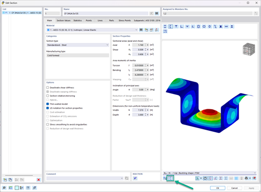
In the "Edit Section" dialog box, you can display the buckling shapes of the Finite Strip Method (FSM) as a 3D graphic.


