The design of cables has not yet been implemented in the "Steel Design" add-on. However, it is possible to design cables in RFEM 6 or RSTAB 9 without using the add-on. The following article shows you how to do it, and what you should pay attention to.
Cable Cross-Section and Material
In the cross-section library of RFEM 6 or RSTAB 9, you can find a selection of cable cross-sections by various manufacturers. For this, select the "Member Sections" cross-section category and filter for the "Cables" shape of the cross-section.
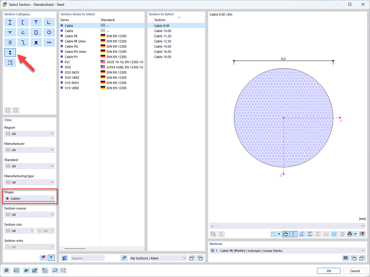
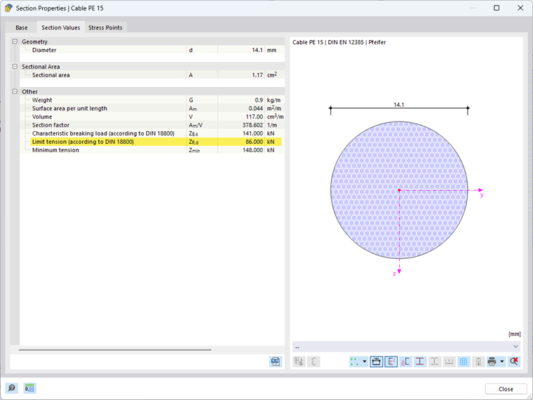
A special feature of the cable cross-sections is that they already include the ultimate tensile force and other cable-specific cross-section parameters.
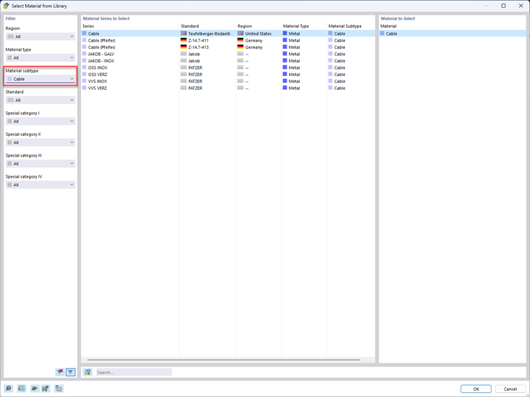
You can also find a selection of cable materials in the material library of RFEM 6 or RSTAB 9 by filtering for the "Cable" material subtype. Make sure that the cable cross-section and the cable material always match, otherwise the specified utlimate tensile force cannot be guaranteed. If you want to use a different material, you can select a non-standard and manufacturer-unspecific cable cross-section.
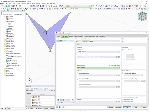
Modeling Cable Structure
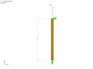
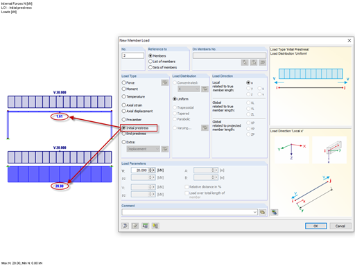
Generally, cables get an intended sag. However, since the exact state of deformation of a cable sobjected to loading is not known initially, it is recommended to model the cable as a straight member. By applying the change in length as an external load, you can influence the cable sag and thus also the internal forces. If a specific final state is requires, such as a maximum sag of 1 m or a maximum tensile force of 10 kN, this can only be achieved iteratively by using the "Axial Strain" load case.
The "Form-Finding" add-on provides you with a more elegant solution for this. It allows you to define and calculate the final states directly. Use the "Form-Finding" add-on to define the desired final state both geometrically and also using the force values.
Cable Design
In the ultimate limit state, it is necessary to design the ultimate tensile force. The design value of the maximum allowable ultimate tensile force can be taken from the cross-section properties of the cable. The design value of the cable force corresponds to the maximum axial force in the cable. You can easily display these as a member internal force within the structural analysis. The design of the maximum tensile load is fulfilled if the maximum axial force in the cable is smaller than the ultimate tensile force of the cable.
Depending on the application, it may be necessary to perform further design checks, such as fatigue, vibration, or detailed design of the cable connections. In that case, please refer to applicable standards.


.png?mw=600&hash=49b6a289915d28aa461360f7308b092631b1446e)