
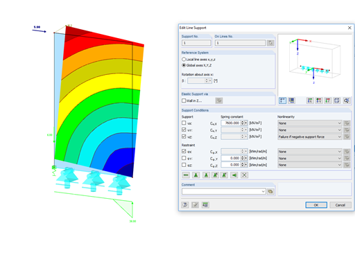
In the case of wall-like load-bearing behavior of the cross-laminated timber plate, special attention must be paid to the shear deformation in the plane of the pane and thus, in particular, to the displaceability of the fasteners.
In the case of wall-like load-bearing behavior of the cross-laminated timber plate, special attention must be paid to the shear deformation in the plane of the pane and thus, in particular, to the displaceability of the fasteners.


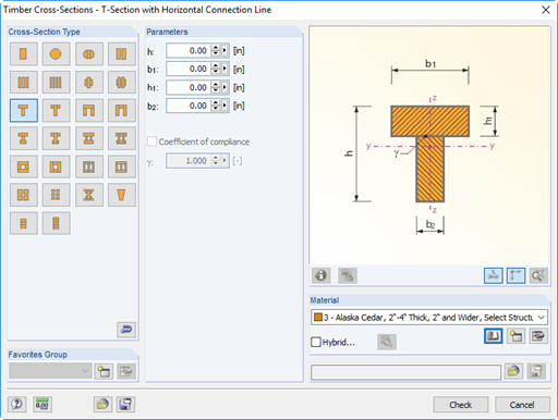
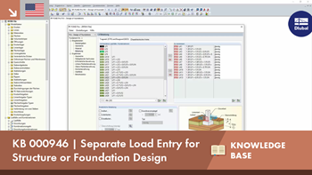
You can define built-up timber cross-sections, for example, channel, T, I, and box girders. Single elements are connected by rigid or semi‑rigid connections. Furthermore, hybrid cross-sections are available. In this case, a submenu provides an option to assign different materials to the individual cross‑section parts.

In RFEM, the oriented strand board (OSB) material is available for the USA and Canada. The material parameters are taken from the "Panel Design Specification manual".
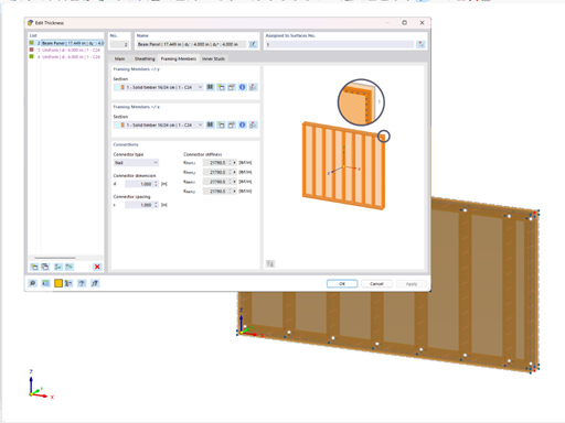
Using the "Beam Panel" thickness type, you can model timber panel elements in 3D space. You just specify the surface geometry and the timber panel elements are generated using an internal member-surface construct, including the simulation of the connection flexibility.
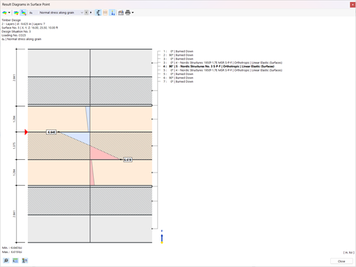
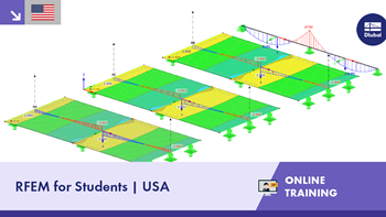
You have the option to perform the fire resistance design of surfaces using the reduced cross-section method. The reduction is applied over the surface thickness. It is possible to perform the design checks for all timber materials allowed for the design.
For cross-laminated timber, depending on the type of adhesive, you can select whether it is possible for individual carbonized layer parts to fall off, and whether you can expect increased charring in certain layer areas.

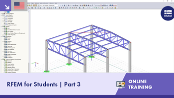
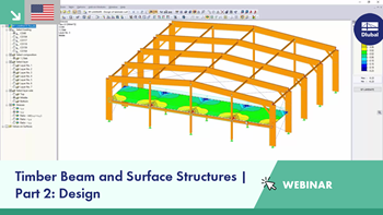
The new generation of 3D FEA software is used for the structural analysis of members, surfaces, and solids.

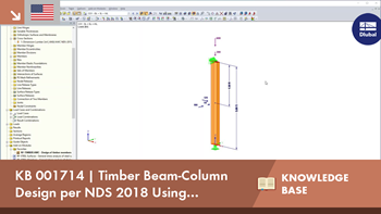
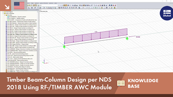
The Timber Design add-on performs the ultimate, serviceability, and fire resistance limit state design checks of timber members according to various standards.

The Structure Stability add-on performs stability analysis of structures. It determines critical load factors and the corresponding stability modes.

The modern 3D structural analysis and design program is suitable for the structural and dynamic analysis of beam structures as well as the design of concrete, steel, timber, and other materials.
The Timber Design add-on performs the ultimate, serviceability, and fire resistance limit state design checks of timber members according to various standards.

Timber design of single-span and wide-span glulam beams according to Eurocode 5 or DIN 1052

Timber design of simple, continuous, and Gerber beams with or without cantilever according to Eurocode 5 or DIN 1052

Timber design of rectangular and circular columns according to Eurocode 5 or DIN 1052

Timber design of coupled purlins and continuous beams according to Eurocode 5 or DIN 1052

Timber design of three-hinged frames with finger joint connections according to Eurocode 5 or DIN 1052

Timber design of stiffening truss bracing according to Eurocode 5 or DIN 1052

Timber design of flat, monopitch, and duopitch roofs according to Eurocode 5


.jpg?mw=350&hash=8f312d6c75a747d88bf9d0f5b1038595900b96c1)


