Answer:
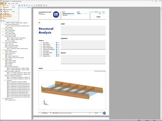
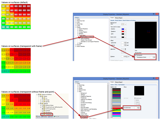
Yes, this is also possible.If you want to edit a graphic in the printout report retroactively, right-click the graphic and click the "Edit" command.


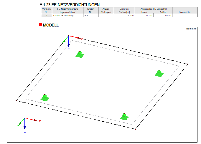
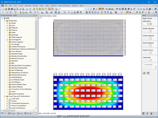
Then, you can adjust the configuration in the Display navigator in this graphic where you can clear the "FE Mesh Refinements" checkbox and return to the report by clicking "Return to Printout Report".

Thus, the display of the FE mesh refinement in the existing graphics can also be edited.


Dlubal_KohlA_]_LI.jpg?mw=350&hash=21d94ec9a723c608496e9e95a21bb1309ab5067a)


.png?mw=350&hash=6f0d685d7bb16d5b49dfc3e9a323beba888a3b4e)


.png?mw=600&hash=49b6a289915d28aa461360f7308b092631b1446e)


