Question
I have calculated a pre-deformed structure according to the second-order analysis with RF‑STABILITY and RF‑IMP. Why are the deformations of the CO smaller than the applied pre-deformation?
Answer:
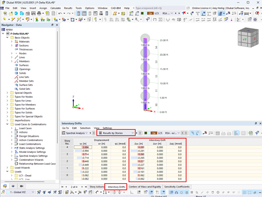
In RF‑IMP, you have selected the "Generate pre-deformed FE mesh" option. In this case, the imperfect structure is considered in the calculation using the deformed FE mesh generated in RF‑IMP. Thus, the CO results refer to the coordinates of the pre-deformed FE mesh and not to the original position in the perfect system.To explain this issue better, I exported the coordinates of the pre-deformed FE mesh nodes from RF‑IMP to Excel. Based on this information, an imperfect structure was created in a new RFEM file and calculated according to the second-order analysis. The left window shows the deformation of the perfect structure considering RF‑STABILITY and RF‑IMP, and the right window shows the result of the imperfect structure. The results are identical.
Do you have any questions?
Using ASCE 7-22 for wind load calculations in RFEM and RWIND involves several specific steps to ensure that your structural designs meet the latest standards provided by the American Society of Civil Engineers. Here’s a step-by-step guide on how to incorporate ASCE 7-22 wind load provisions into RFEM and RWIND simulations:
In this article, you will learn how to model and design cable structures in RFEM 6 or RSTAB 9.
This article describes and explains the influence of bending stiffness of cables on their internal forces. Furthermore, the text provides information on how this influence can be reduced.
The ASCE 7-22 Standard [1], Sect. 12.9.1.6 specifies when P-delta effects should be considered when running a modal response spectrum analysis for seismic design. In the NBC 2020 [2], Sent. 4.1.8.3.8.c gives only a short requirement that sway effects due to the interaction of gravity loads with the deformed structure should be considered. Therefore, there may be situations where second-order effects, also known as P-delta, must be considered when carrying out a seismic analysis.
In RFEM, the oriented strand board (OSB) material is available for the USA and Canada. The material parameters are taken from the "Panel Design Specification manual".
The "Bracing in Cells" function allows you to generate diagonal bracing with just a few clicks. You can find this feature under Tools → Generate Model – Members → Bracing in Cells.
In RFEM and RSTAB, you can visualize the flow field quantities of pressure, velocity, turbulence kinetic energy, and turbulence dissipation rate for the wind simulation.
The clipping planes are aligned with the respective wind direction.
In the ultimate configuration of the steel joint design, you have the option to modify the limit plastic strain for welds.
Recommended Products for You