Design Background
In addition to the general technical approvals of the individual producers, the design of point-supported fittings is regulated in DIN 18008 [1]. This German standard specifies two different ways:
- Annex B – Verification / validation of finite element models
- Annex C – Simplified method
In addition to the various design options, there are constructional provisions—especially for plate fittings—specifying the geometrical arrangement on a glass pane or the formation in the edge area.
Initial Data Used for Analysis
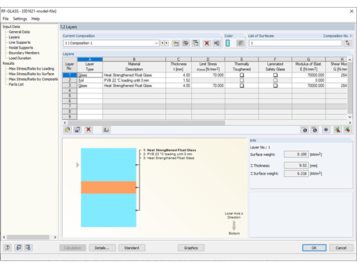
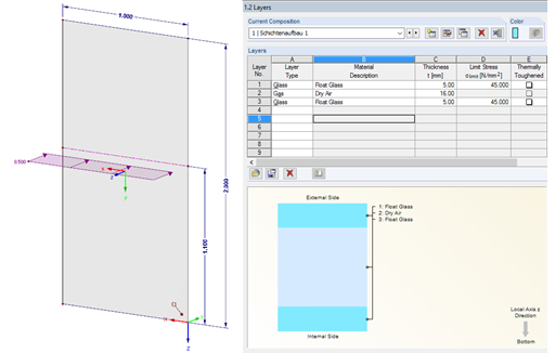
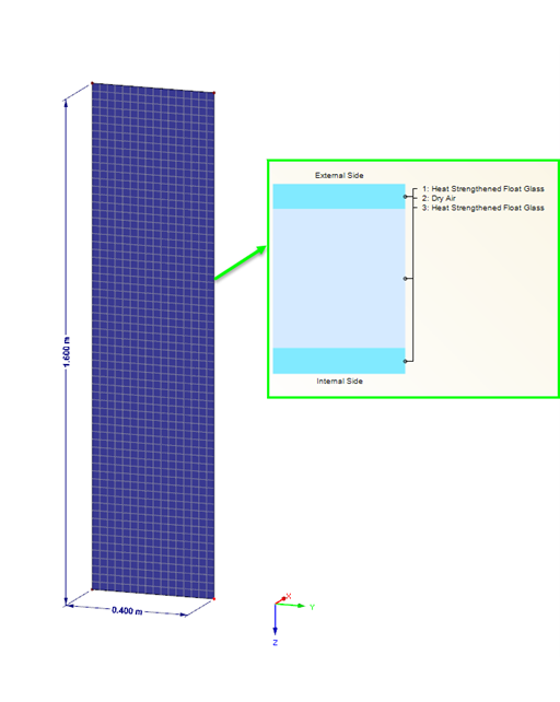
Laminated safety glass from heat-strengthened float glass 2 x 8 mm
Point fixing PH 793 by Glassline GmbH (approval Z-70.2-99 [3]), cylindrical head Ø 52 mm, drilling Ø 25 mm
Design load qd = 4.5 kN/m²
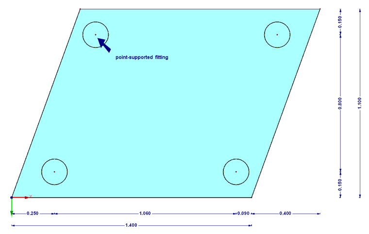
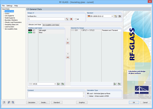
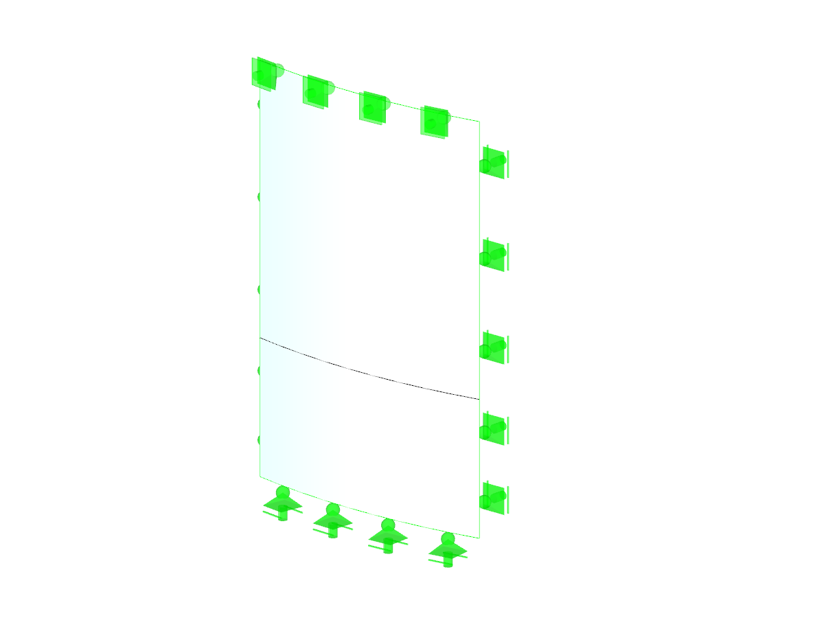
Modeling in RFEM According to Simplified Method
In the case of glass pane design according to the simplified method described in DIN 18008, Annex C [1], the pane may be analyzed without the drilling holes. The existing glass fittings are represented by springs. The existing spring stiffness is specified in the technical approval. In our example, it gives the following result:
CZ,max = 1/24,372 + 1/3,015 = 2,683 N/mm
CZ,min = 1/15,386 + 1/1,592 = 1,443 N/mm
CZ,sel = 2,000 N/mm
CV;x,y = 344 N/mm
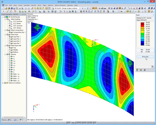
The following result values are calculated on the basis of the mentioned parameters.
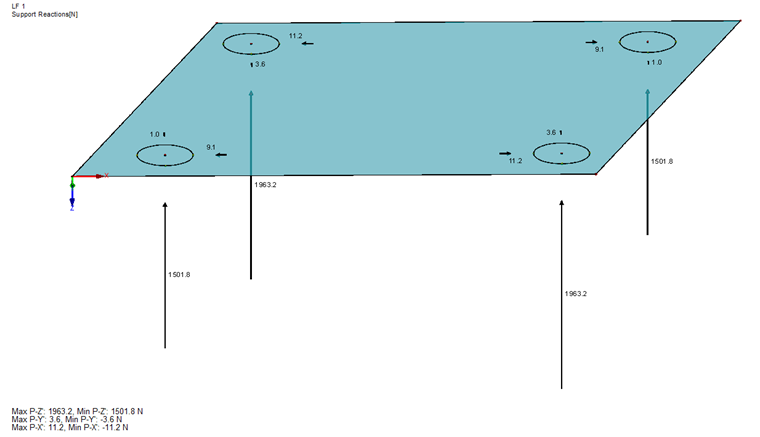
All relevant stress ratios can now be calculated using the formulas and parameters provided by DIN 18008, Annex C [1].
Stress component FZ:
Stress component Mres:
Due to the hinged support around axes x, y, and z, there is no additional moment Mres.
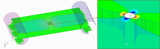
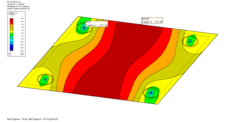
Stress concentration in the drilling hole area:
σg = σg(3d) ∙ δg ∙ k = 9.6 ∙ 8 / 10.8 ∙ 1.6 = 11.4 N/mm²
The governing design stress value in the fitting area then results from the sum of the individual components.
Ed = 38.8 + 0.1 + 11.4 = 50.3 N/mm²
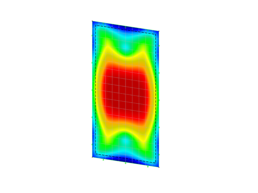
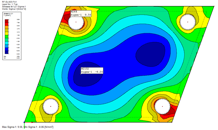
As the final step, the moment in the span must be considered. In this case, the moment has to be determined on a statically defined system.
The governing stress in the span area is Ed = 16.5 N/mm².
The allowable stress for laminated safety glass is calculated as:
Thus, it gives the result of the total design ratio of the glass η = 0.98.
In addition to the general stress analysis performed here, you can perform additional designs for the exact dimensions of the glass pane. For this, you can follow the standard.
Conclusion
Annex C of the German standard DIN 18008 provides very simple tools for designing point-supported glass fittings. By using the table values, you can very quickly estimate the structural behavior of the glass pane and determine the design ratio. Another option is specified in Annex B of the standard. This design method based on a finite element model will be explained in the next part of this article.


.png?mw=350&hash=744ef4cb87267613ad6fa22fe7d54607ce60f3cc)