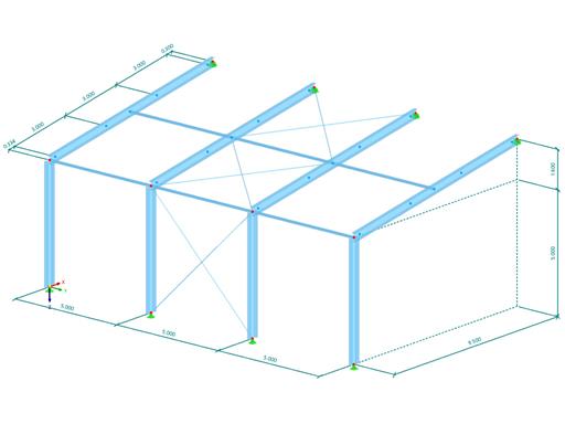
Geometry
The monopitch roof plan has dimensions of 9.5 m x 15 m. The difference in height between the eaves and the ridge is set to 1.6 m, which corresponds to an inclination of 9.56°.
The main beam spacing is 5 m. ZL purlins for sandwich elements are to be placed on these main beams at a spacing of 3 m. Therefore, the main beams are divided by internal nodes of the "On Member" type.

The purlins are arranged alternately. This means that the purlin cross-section must additionally be rotated by 180° in every second bay, so that the purlins fit into each other for the overlap. In the attached file below under Models to Download, a new cross-section is used instead of the member rotation, where the dimensions of the flanges are entered in reverse order.
First, the purlins are stressed from node to node. A ZL section with the following dimensions is applied:

It is necessary to do the overlapping of the cross-sections already in the RFEM model. Some purlin manufacturers recommend the following:
The first coupled purlin is extended by 0.15 x L into the first inner bay, and the second purlin is extended by 0.1 x L into both adjacent bays.
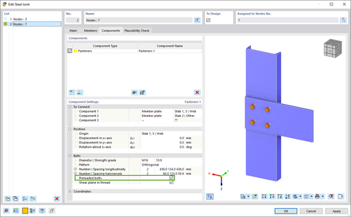
Two horizontal bolt rows are arranged above the support and on each of the specified extensions. An edge distance of 32 mm is additionally specified at the free end of the coupled purlin. Thus, the resulting overlap lengths are 532 and 782 mm.
Once these extensions are shown on the model, the corresponding member hinges must be defined.

All coupled purlins have a scissor hinge at the node of the main beam. This ensures that the bending moment is not transferred as torsion into the beam.
The end of the coupled purlin also has a hinge that transfers shear forces only.
The stiffening by the sandwich panels is assumed to be a member support of cu,y = 1,000 kN/m² and Cφ,x = 1.70 kNm*rad-1*m-1.
In order to also consider and design the purlin shoes for the connection, they are also modeled with the total length of 13 cm.
Eccentricities
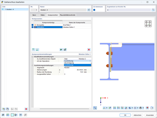
In steel joint design, the exact position of the modeled centroidal axes is always used. Therefore, it is necessary to already specify the eccentricities in the main model.
Using relative eccentricities is especially helpful for asymmetrical cross-sections with uneven distances to the centroid.
Since a gap of at least 6 mm is required between the purlin's bottom flange and the beam's top flange, the outer purlins get a relative and absolute eccentricity in the local z-axis direction of -6 mm related to the top beam flange.
Then, a transverse offset related to the outer purlins of additionally ey = -4 mm and ez = -2 mm are assigned to the central purlins.
The same eccentricity type is also allocated to the purlin shoes, but for them the additional offset is ey = -80.5 mm and ez = 6 mm.

Loading
Load case for self-weight: additional load from sandwich panels of 0.15 kN/m²
Load case for snow: 0.68 kN/m²
Load case for wind suction: simplified by -0.45 kN/m² acting on the entire roof area
All loads are applied to the coupled purlins using the "Member Loads from Area Load" load wizard.
The load cases are combined in two load combinations as follows:
- CO1 = 1.35 × LC1 + 1.5 × LC2
- CO2 = 0.9 × LC1 + 1.5 × LC3
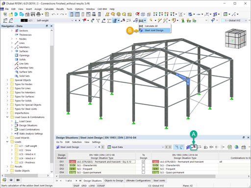
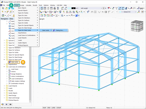
Input of Steel Joints
In the example, the connection is entered at a node for which all seven members are taken into account.
The member type is set as "Continuous" for all members, and both member ends of the main beam are set to be supported.
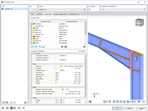
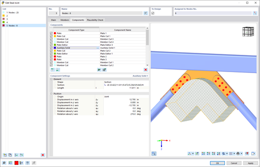
Pressure contact may occur in the overlapping area of the coupled purlins. It can be modeled by means of "Fasteners" components by setting the number of bolts to 0, resulting in a surface contact acting only with failure under tension.
In total, five components of the same "Fasteners" type are therefore required in the present example.
- Bolting of purlin shoe to beam flange
- Bolting of purlin shoe to both coupled purlins
- Outer bolt rows at ends of overlap
- Contact between both top flanges of coupled purlins
- Contact between both bottom flanges of coupled purlins

In the case of thin-walled elements, it is not recommended to perform a design with the default plastic limit strain of 5%. Therefore, the limit value is reduced to 1%. Furthermore, a buckling analysis should be performed.
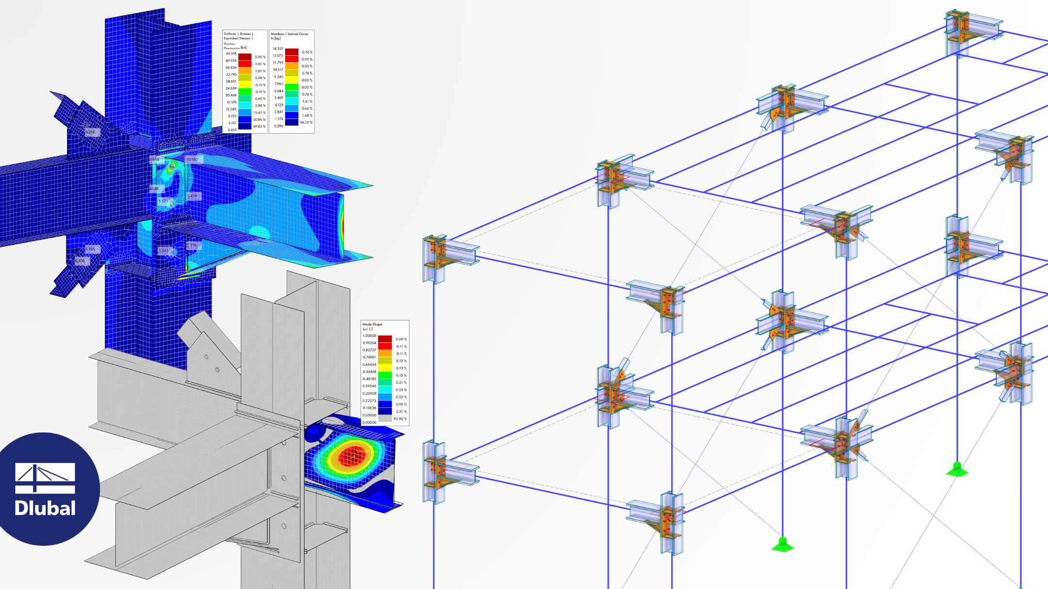
Results
The result of the stress analysis is as follows:

The German Wirth load-bearing capacity table specifies an allowable uniformly distributed load of 3.43 kN/m. In contrast, the model is stressed by 3.75 kN/m. As a consequence, either the distance of the purlins must be reduced, or a higher material strength, or a stronger cross-section must be selected. The third option is applied to the model, and the sheet thickness of the cross-section is increased to 2.5 mm. It is also necessary to change eccentricity no. 2 to ey = -3.5 mm and ez = -2.5 mm, and eccentricity no. 3 to ey = -80.25 mm and ez = 6 mm.

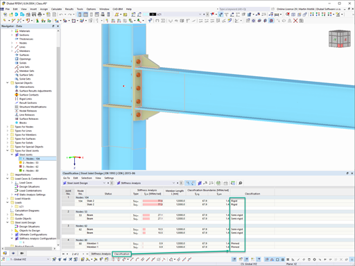
When performing the simplified buckling analysis, a stability problem will appear. The first two mode shapes are beyond the connection node; however, mode shapes no. 3 and 4 are within the connection zone and thus require closer analysis.

For example, a GMNIA analysis (Geometrically and Materially Nonlinear Analysis with Imperfections included) may be performed on the submodel, which is beyond the scope of this technical article.


.png?mw=350&hash=b2324c4db119938012b5490afaa56e9aa826cdcc)


.png?mw=600&hash=49b6a289915d28aa461360f7308b092631b1446e)


