14 Results
View Results:
Sort by:

Compliance with building codes, such as Eurocode, is essential to ensure the safety, structural integrity, and sustainability of buildings and structures. Computational Fluid Dynamics (CFD) plays a vital role in this process by simulating fluid behavior, optimizing designs, and helping architects and engineers meet Eurocode requirements related to wind load analysis, natural ventilation, fire safety, and energy efficiency. By integrating CFD into the design process, professionals can create safer, more efficient, and compliant buildings that meet the highest standards of construction and design in Europe.

With the Steel Design add-on, you can design structural steel components in the event of fire using the simple design methods according to Eurocode 3. The component temperature at the time of the design check can be determined automatically according to the temperature-time curves specified in the standard. In addition to considering a cladding for fire protection, it is also possible for you to take account of the beneficial properties of hot-dip galvanization.

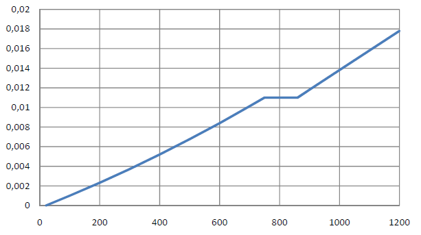
Steel has poor thermal properties in terms of fire resistance. The thermal expansion for increasing temperature is very high compared to that of other building materials, and might result in effects that were not present in the design at normal temperature due to restraint in the component.As temperature increases, steel ductility increases, whereas its strength decreases. Since steel loses 50% of its strength at temperature of 600 °C, it is important to protect components against fire effects. In the case of protected steel components, the fire resistance duration can be increased due to the improved heating behavior.

The reinforced concrete design for fire situations is carried out according to the simplified method based on EN 1992-1-2, Clause 4.2. The "zone method" described in Annex B.2 is used: The cross-section is subdivided into a number of parallel zones of equal thickness, and their temperature-dependent compressive strength is determined. The reduced load-bearing capacity in the event of fire exposure is thus represented by a reduced structural component's cross-section with reduced strengths.
The RF-/STEEL EC3 add‑on module allows for the fire protection design of structural steel components. The simplified analysis is performed by determining the steel temperature iteratively for a particular point of time.
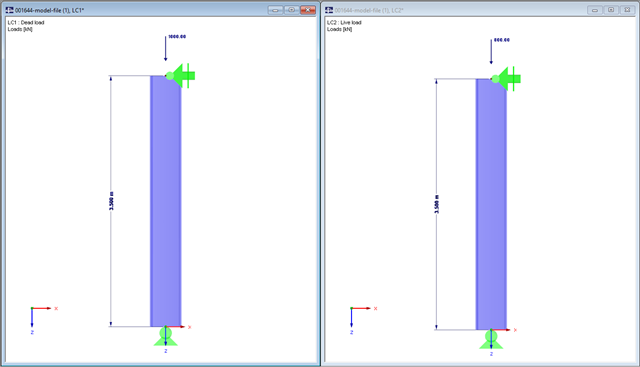
In this technical article, a hinged column with a centrally acting axial force will be designed by means of the RF-/STEEL EC3 add-on module according to EN 1993-1-2. We will use the National Annex of Germany here.

With RF-/STEEL EC3, you can utilize nominal temperature-time curves in RFEM and RSTAB. The standard time-temperature curve (ETK), the external fire curve and the hydrocarbon fire curve are implemented. Moreover, the program provides the option to directly specify the final temperature of steel.

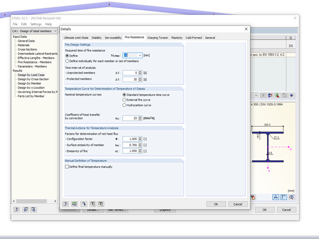
The fire resistance design can be performed according to EN 1993-1-2 in RF-/STEEL EC3. The design is carried out according to the simplified calculation method for the ultimate limit state. Claddings with different physical properties can be selected as fire protection measures. You can select the standard temperature-time curve, the external fire curve, and the hydrocarbon curve to determine the gas temperature.
You can apply nominal temperature‑time curves in RFEM or RSTAB using RF‑/STEEL EC3. For this, the standard time-temperature curve (ETK), the external fire curve and the hydrocarbon fire curve are implemented in the program. Based on these temperature curves, the add‑on module can calculate the temperature in the steel cross‑section and thus perform the fire design using the determined temperatures. This article explains the thermal behavior of structural steel, as this has a direct impact on the calculation of component temperatures in RF‑/STEEL EC3.
![Section Factor Am/V for Unprotected Steel Components (Source: [5])](/en/webimage/009429/2418748/01-en-1-png.png?mw=640&hash=0fa099ecd1abc5310bef76fe3f22b7fe0c925df6)
Using RF-/STEEL EC3, you can apply nominal temperature-time curves in RFEM or RSTAB. For this, the standard time-temperature curve (ETK), the external fire curve, and the hydrocarbon fire curve are implemented in the program. Based on these diagrams, the add-on module can calculate the temperature in the steel cross-section and thus perform the fire design. This article explains the behavior of protected and unprotected steel cross‑sections.
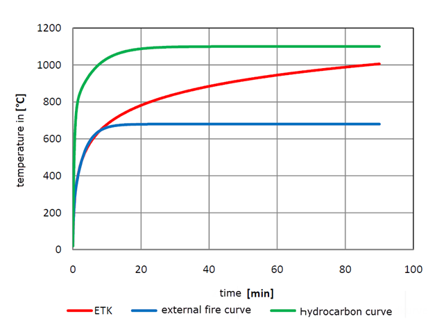
Using RF-/STEEL EC3, you can apply nominal temperature-time curves in RFEM or RSTAB. The standard time-temperature curve (ETK), the external fire curve and the hydrocarbon fire curve are implemented. Moreover, the program provides the option to directly specify the final temperature of steel. This steel temperature can be calculated using the parametric temperature-time curve, as described in the Annex to DIN EN 1992-1-2. The different fire exposures are explained in this article.
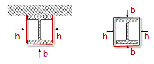
For unprotected I‑sections, the standard provides the correction factor ksh according to Equation 4.26a in Section 4.2.5.1 (2) to consider the shadowing effect. The term [Am/V]b is used there. This section factor includes Am, which represents the box enclosing the cross‑section (Index b = boxed). In the case of a three-sided fire exposure (a girder with a massive ceiling), the flange surface not exposed to fire is not taken into account when determining [Am/V]b.
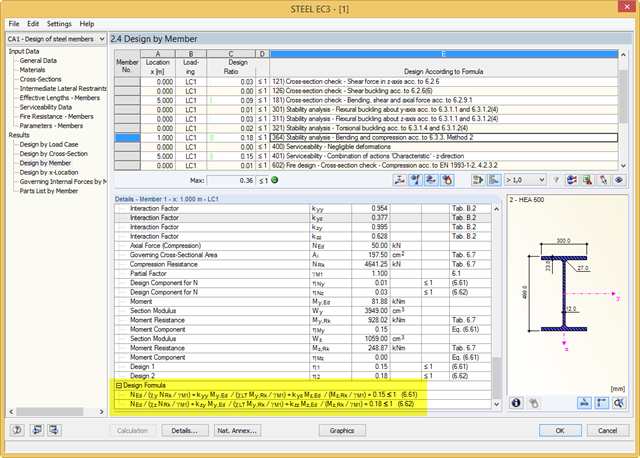
RF-/STEEL EC3 performs the classification, cross‑section designs, serviceability limit state designs, and fire resistance designs of members. For each design, the program shows a result table with the relevant values and classification numbers, including information regarding the respective standard clause. In order to identify the conjunction of various standards easily, there is a final design equation, including all terms, at the end of the table.
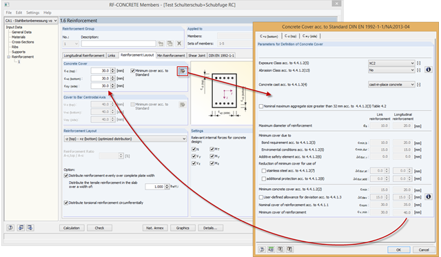
RF-/CONCRETE automatically determines the minimum concrete cover according to the standard. The calculation is based on the exposure class, the abrasion class, and the concrete cast.