15 Results
View Results:
Sort by:
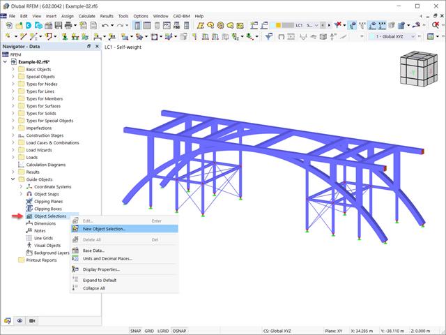
In the RFEM 6 and RSTAB 9 programs, it is possible to group objects based on different criteria. Hence, objects that meet the defined criteria can be selected and edited at the same time. This is possible with the “Object Selection” tool, which is comparable to “Special Selection” in RFEM 5. This article will show you how to group objects with “Object Selection" as a new guide object of RFEM 6 or RSTAB 9.

Complex structures are assemblies of structural elements with various properties. However, certain elements can have the same properties in terms of supports, nonlinearities, end modifications, hinges, and so on, as well as design (for example, effective lengths, design supports, reinforcement, service classes, section reductions, and so on). In RFEM 6, these elements can be grouped on the basis of their shared properties and thus can be considered together for both modeling and design.

Seismic Analysis in RFEM 6 is possible using the modal analysis and the response spectrum analysis add-ons. As a matter of fact, the general concept of the earthquake analysis in RFEM 6 is based on the creation of a load case for the modal analysis and the response spectrum analysis, respectively. The standard groups for these analyses are set in the Standards II tab of the model’s Base Data.

In RF‑TENDON and RF‑TENDON Design, you can review and adjust the code‑dependent factors, calculation parameters, and calculation methods using the "Code" button. You can display the settings and adjustment options according to a chapter of a code, selecting the "Grouping" option in the dialog box.
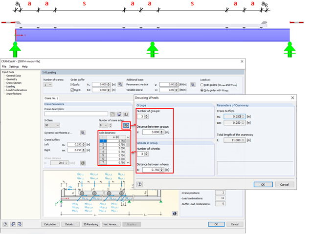
In CRANEWAY, the "Grouping Wheels" dialog box allows you to generate efficient groups with equal intervals.
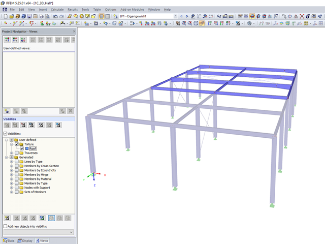
User-defined visibilities facilitate program handling. Once created, any model groups can be quickly hidden or shown. This facilitates, among other things, the analysis of the results in larger 3D structures, as well as the creation of the report. When changing the geometry, the existing visibilities may have to be updated.
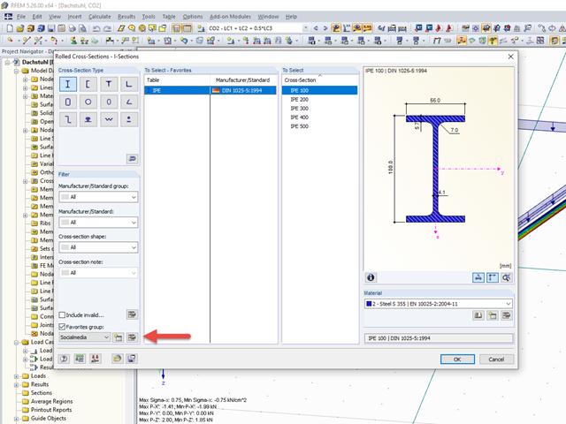
The cross-section library in RFEM 5 and RSTAB 8 offers the option to save certain cross-section selections in different favorites groups.
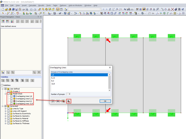
When modeling in RFEM, double lines may be created. To quickly find and delete them, if necessary, RFEM 5 allows you to export overlapping lines. This is possible, for example, in Excel or in a separate group of sections.
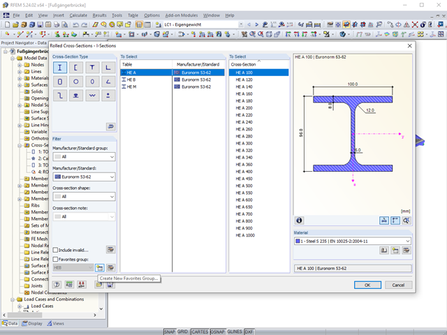
The "Filter" option in the cross‑section library allows you to show only cross‑sections of certain standards, shapes, or types. In the same window, you can also select the material.
An effective way to represent reinforcement graphically is to arrange it in groups.
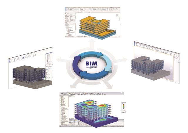
The building and construction industry is increasingly digitized. Structural engineers, a smaller group in the construction industry, are not always considered to be engineers who follow the latest trends immediately. There is often good reason for this. Many consider this to be the reason that topics such as utilizing the BIM method are not yet the standard in structural engineering. However, the past few years have shown that a process of rethinking has begun, and new digital trends are being picked up and applied.

As in RFEM, load combinations can be generated automatically in RF‑PIPING. This feature is activated by default and creates the recommended load and result combinations for piping design. It is necessary to assign the relevant action category to load cases in order to generate the correct combinations. To do this, new action categories have been implemented specifically for loads on piping.
Pressure temperature conditions are generated as the sets of the first (second, third, and so on) load case of the "Pressure" category and the first (second, third, and so on) load case of the "Temperature" category. The default setting can be reviewed or adjusted in the "Grouping of Thermal and Internal Pressure Load Cases for Operating Combinations" dialog box. You can access this dialog box by clicking the corresponding button in the "Piping Load Combinations" tab of the "Load Cases and Combinations" dialog box. This dialog box is automatically offered to check your entries in the case of any change of the load case from the "Pressure" or "Temperature" category.
Pressure temperature conditions are generated as the sets of the first (second, third, and so on) load case of the "Pressure" category and the first (second, third, and so on) load case of the "Temperature" category. The default setting can be reviewed or adjusted in the "Grouping of Thermal and Internal Pressure Load Cases for Operating Combinations" dialog box. You can access this dialog box by clicking the corresponding button in the "Piping Load Combinations" tab of the "Load Cases and Combinations" dialog box. This dialog box is automatically offered to check your entries in the case of any change of the load case from the "Pressure" or "Temperature" category.
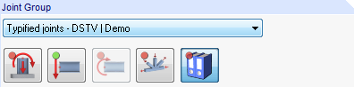
Starting with program version X.06, joint groups are clearly identified in RF‑/JOINTS.
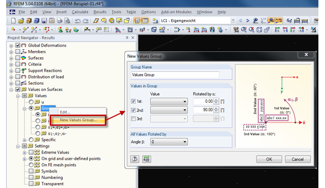
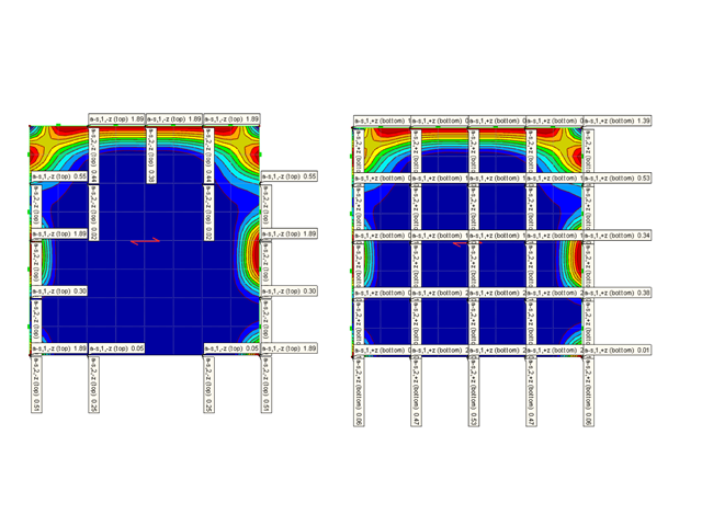
RFEM provides the option to display up to three result values of the surface results in each group. Four groups are preset under "Groups" in the Results Navigator.

In RF-CONCRETE Surfaces, you can use the "Filter Points" function when evaluating results by points. This filter function allows for a user-defined group of points that can be defined in the result window. You can select the filter in Window 2.3 Required Reinforcement by Points, among others.