回复:
原则上,截面是一个单元,例如杆件,并且可以通过相同的方式创建。 首先,需要对象的接口。 对于杆件,这将是 IModelData,对于截面,这将是 ISections。 该接口可以在 IModel3 中找到:
子测试部分()' 从打开的模型中获取接口并锁定许可证/程序Dim iModel As RFEM5.IModel3Set iModel = GetObject(, "RFEM5.Model")iModel.GetApplication.LockLicense 出错时转到 E Dim iSecs As RFEM5.ISsection设置 iSecs = iModel.GetSections()
首先删除之前创建的所有截面,然后创建两个新的截面。
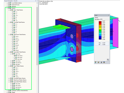
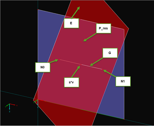
第一部分应该是具有可见截面面积的实体截面(见图 01)。 输入方法与 RFEM 类似。 选择类型为“SectionOnSectionalArea”,截面的角点通过使用“边缘点”设置,并使用“向量”定义截面的方向:
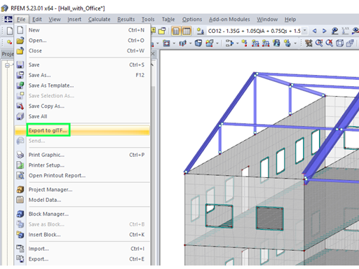
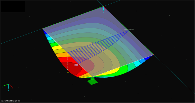
' 首先删除所有部分iSecs.PrepareModification iSecs.DeleteObjects(“全部”)iSecs.FinishModification ' 在实体上设置截面Dim sec As RFEM5.Sectionsec.EdgePointA.X = 2sec.EdgePointA.Y = 5sec.EdgePointA.Z = 0sec.EdgePointB.X = 2sec.EdgePointB.Y = 8sec.EdgePointB.Z = 0 sec.no = 1sec.Name = "实体截面"sec.Plane = GlobalPlaneInPositiveXsec.ShowValuesInIsolines = Falsesec.Type = SectionOnSolidSectionLinesec.ObjectList = "1" iSecs.PrepareModificationiSecs.SetSection 秒iSecs.FinishModification正如从其他单元中已知的那样,新的截面最终被传递到 Prepare-/FinishModification 块中。 创建面的截面作为第二个截面(见图 02)。 为此必须使用类型“SectionViaSurfacePlane”。 除了截面方向的矢量外,还必须选择面截面结果的显示平面。 在下面的示例中,xy 平面是通过设置 "GlobalPlaneInPositiveX" 来选择的。
' 在面上设置截面sec.EdgePointA.X = 2sec.EdgePointA.Y = 0sec.EdgePointA.Z = 0sec.EdgePointB.X = 2sec.EdgePointB.Y = 3sec.EdgePointB.Z = 0 sec.no = 2sec.Name = "面的截面"sec.Plane = GlobalPlaneInPositiveX sec.ShowValuesInIsolines = Truesec.Type = SectionViaSurfacePlanesec.ObjectList = "1" sec.Vector.X = 0sec.Vector.Y = 0sec.Vector.Z = 1 iSecs.PrepareModificationiSecs.SetSection 秒iSecs.FinishModification
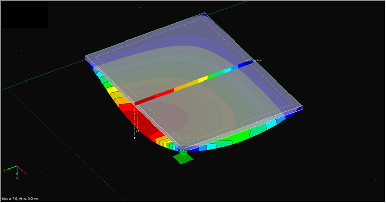
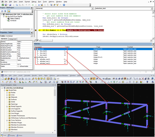
也可以通过使用接口 "IResults2" 的单独方法 "GetResultsInSection" 来获取截面的结果。 接下来计算作用在面上的剪力。 通过“ContinuousDistributionWithinObjects”将内力的分布设置为“面内连续”:
' 得到结果Dim iCalc As ICalculation2设置 iCalc = iModel.GetCalculation 将 iRes 调暗为 IResults2设置 iRes = iCalc.GetResultsInFeNodes(LoadCaseType, 1) Dim secRes() As RFEM5.SectionResultsecRes = iRes.GetResultsInSection(2, AtNo,剪切力Vy、对象内连续分布、假)
在下载下,您可以找到 Excel 宏和测试文件,以帮助您理解程序。


Dlubal_KohlA.png?mw=350&hash=6f6b192b31c8bbcb1c62aa6cf9fbfb1d9f859880)


.png?mw=512&hash=ea9bf0ab53a4fb0da5c4ed81d32d53360ab2820c)