Do you have any questions about Dlubal products or need assistance in selecting the right one for your project?
I'm here to help. You can easily reach me through the contact options provided below.
Looking forward to hearing from you!


Cold-Formed Steel Member Design According to EC3


_LI.jpg?mw=1024&hash=95d30e618712ed54ece3cefe83432399fbdd0085)

RF-/STEEL Cold-Formed Sections | Features
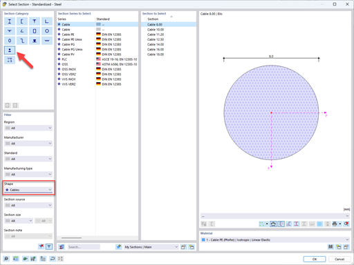
- Available for cold-formed L, Z, C, channel, top-hat, and CL sections from the cross-section database, as well as for general cold-formed (non-perforated) SHAPE-THIN-9 sections
- Determination of the effective cross-section considering the local buckling and the distortional buckling
- Cross-section ultimate limit state, stability, and serviceability limit state designs according to EN 1993‑1‑3
- Design of local transverse forces for webs without stiffening
- Available for all National Annexes included in RF-/STEEL EC3
- Module extension RF-/STEEL Warping Torsion (license required) for stability analysis according to second-order analysis as stress analysis including consideration of the 7th degree of freedom (warping)

RF-/STEEL Cold-Formed Sections | Input
Since RF-/STEEL Cold-Formed Sections is fully integrated in RF-/STEEL EC3, the data are entered in the same way as for the usual design in this module. It is only necessary to select the design option for cold-formed cross-sections in the Details dialog box.

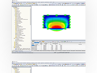
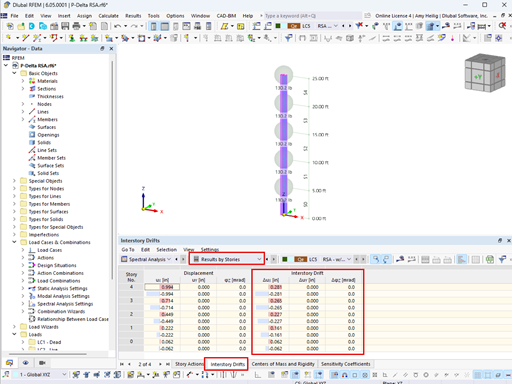
RF-/STEEL Cold-Formed Sections | Results
The design results are displayed in RF-/STEEL EC3 in the usual way.
Among other results, the corresponding result windows include the effective cross-section properties due to axial force N, bending moment My, bending moment Mz, internal forces, and design summary.

.png?mw=192&hash=f63e4a3f1836233005de32f60201d5392e507cf1)
Calculate Your Price
The price is valid for United States. Prices are only valid for the software usage in United States. You can get exact prices after signing in. Please log on to your account at Dlubal Software to generate an updated quote.

Implemented Standards for Reinforced Concrete Design
Standards for Concrete Design
Annexes for EN 1992-1-1


Use the "Independent mesh preferred" option in the FE mesh settings to create an independent FE mesh for the integrated objects. This allows you to generate a significantly more detailed and precise FE mesh for individual objects that are integrated into one another.
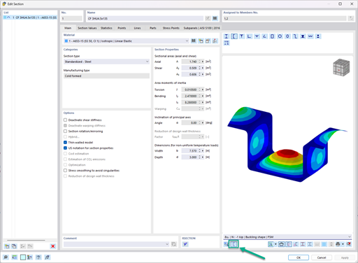
In the "Edit Section" dialog box, you can display the buckling shapes of the Finite Strip Method (FSM) as a 3D graphic.

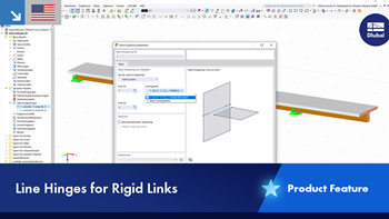
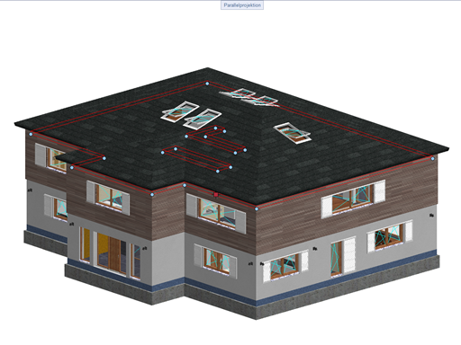
In RFEM 6 and RSTAB 9, you have the option to enter "Visual Objects" as guide objects. You can import the file formats 3ds, stl, and obj.
These objects allow you to create a better reference to the dimensions.

- Design of five types of seismic force-resisting systems (SFRS) includes Special Moment Frame (SMF), Intermediate Moment Frame (IMF), Ordinary Moment Frame (OMF), Ordinary Concentrically Braced Frame (OCBF), and Special Concentrically Braced Frame (SCBF)
- Ductility check of the width-to thickness ratios for webs and flanges
- Calculation of the required strength and stiffness for stability bracing of beams
- Calculation of the maximum spacing for stability bracing of beams
- Calculation of the required strength at hinge locations for stability bracing of beams
- Calculation of the column required strength with the option to neglect all bending moments, shear, and torsion for overstrength limit state
- Design check of column and brace slenderness ratios


