Model Import to RFEM
In order to design a structure created in Allplan, you can import it into RFEM as an IFC file. When doing so, you can also export selected drawing files from Allplan.
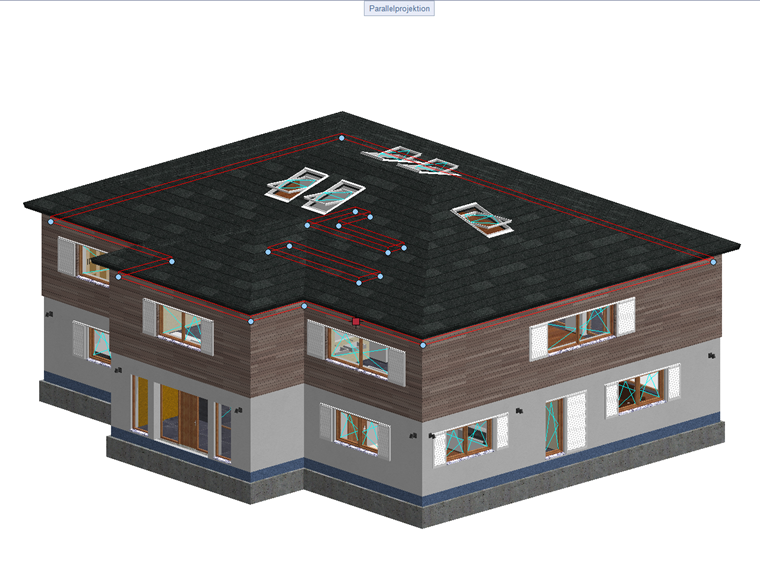
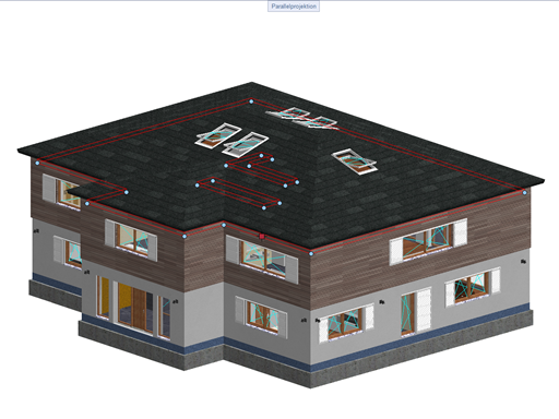
In the following text, a floor slab is designed. For this, the slab to be designed and the load-bearing walls below it are exported from Allplan as an IFC file. You can also export a 2D DXF file in order to transfer the dimensions of the floor slab as a background layer to RFEM.
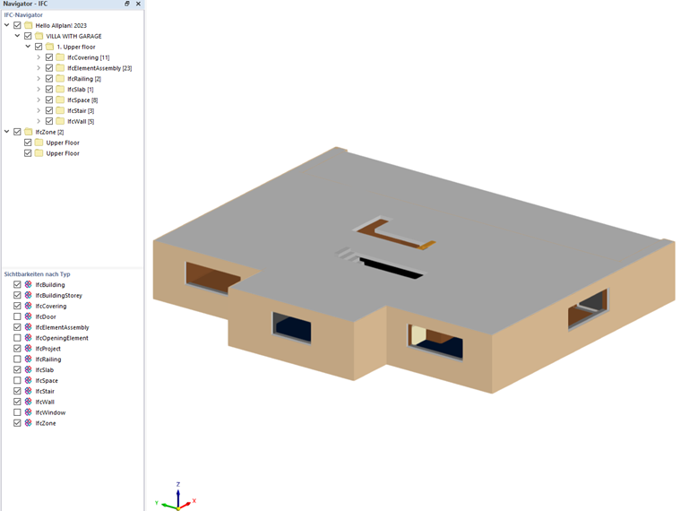
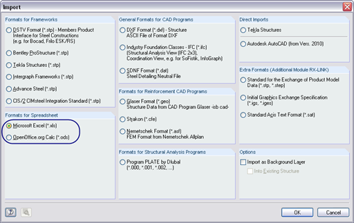
The IFC file can be imported into RFEM. After the import, the file is displayed in the integrated IFC viewer.
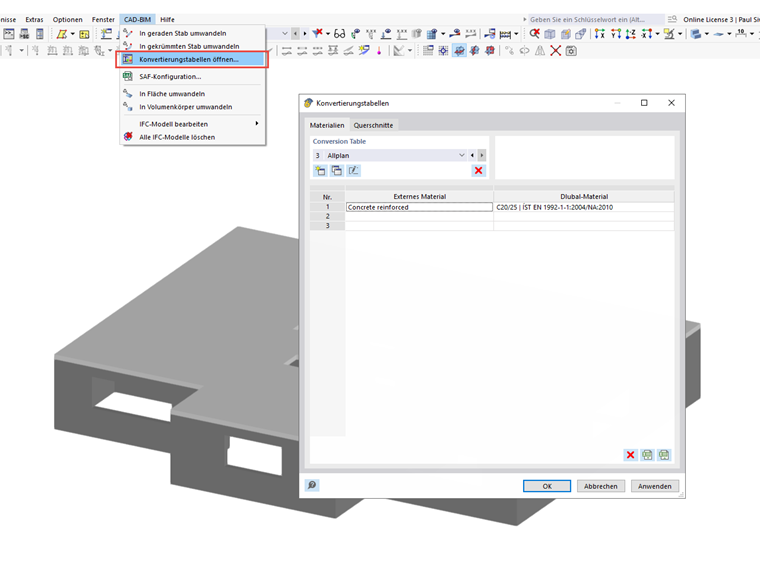
The material defined in Allplan can be assigned to a Dlubal material using the conversion tables (CAD BIM → Conversion Tables). Thus, the assigned material is generated automatically when converting the IFC objects. The entries in the conversion tables are defined once, and can be imported and exported to any work station, if necessary.
First, you should check whether there are structurally irrelevant objects available in the IFC model. The IFC objects that you no longer need can be hidden in the IFC navigator. In the example model, the individual wall layers, such as insulation, air space, cladding, and stairs, are hidden, as they are not necessary for the structural model. Thus, the remaining objects for the slab and all load-bearing walls form the basis of the structural model.
In general, CAD programs use Coordination View for exporting your data to an IFC file. The Coordination View describes a model that corresponds to the subsequent real solid model in its position and shape. A structural model consisting of members and surfaces is usually created for the calculation.
For this, it is necessary to convert the IFC solids into surfaces or members.
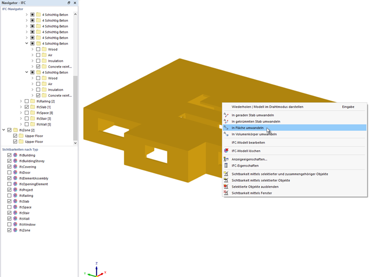
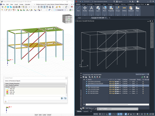
When converting the IFC solids, surfaces are created in the centroidal axis of the solids. This means that the system lines of the walls (green) have to be shortened or extended in the structural model.
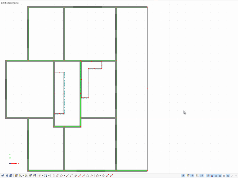
It is not necessary to model walls for the slab design, if you can model the structural behavior of the walls close to reality. You can use the "Stiffness via Fictitious Wall" support type for this. The floor slab is supported on the system lines of the walls.
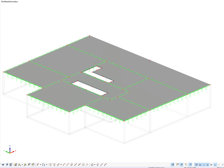
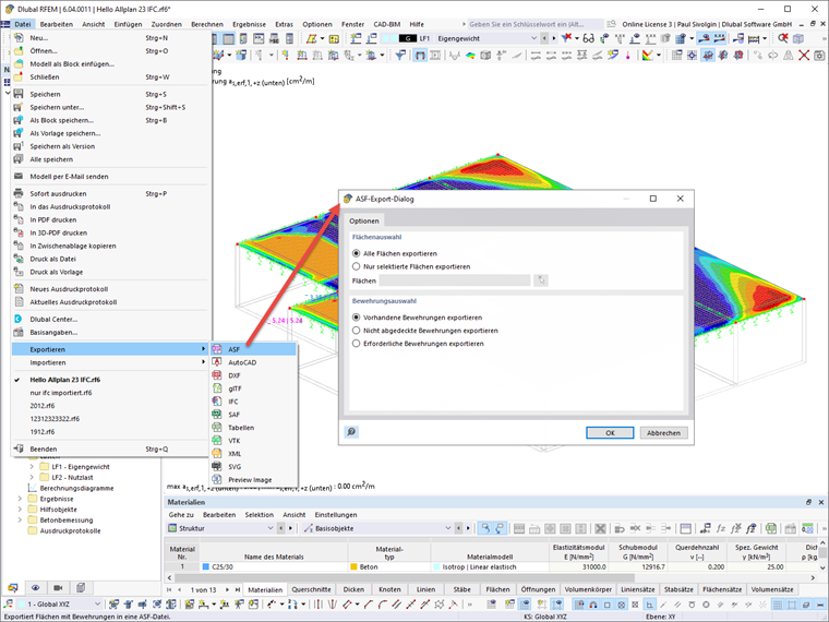
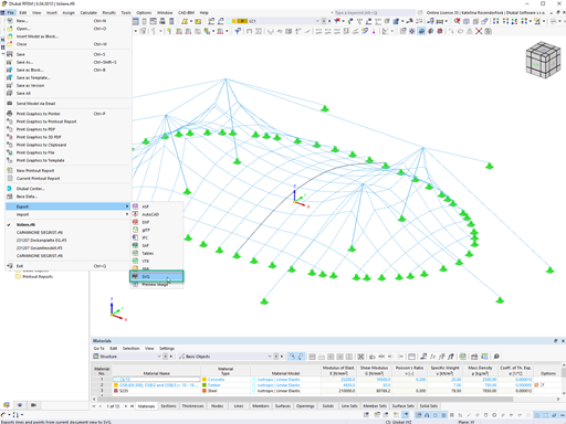
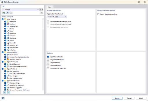
Then, you can load and design the floor slab. To import the reinforcement results from RFEM into Allplan, you can use the ASF export. It is possible to export the results of one or more surfaces as an ASF file. You can also export the values for the provided, not covered, or required reinforcement.
Transfer of Results to Allplan
The ASF file exported from RFEM can be imported into Allplan. The results are imported using the FEA data import in Allplan. Before you start the import, select an active drawing file of the reinforcement. The drawing file of the slab can remain active in the background. In the "Teamwork" tab, the ASF file is imported using the FEA Import.
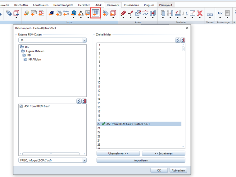
You can open the imported ASF file in the "Reinforcement" tab via the colored reinforcement images. On the right, you can see two colored reinforcement images that represent the reinforcement content from the ASF file.
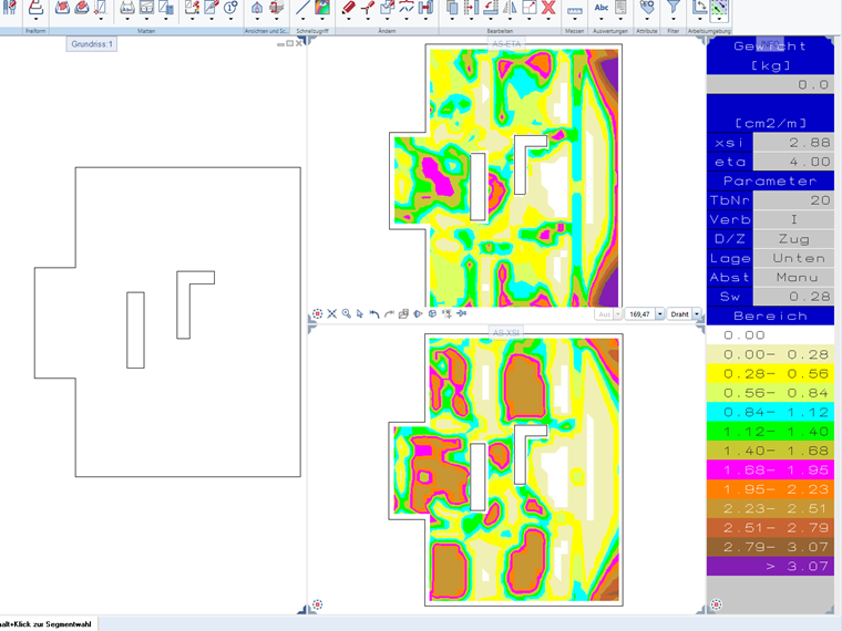
This display allows for the interactive creation of reinforcement. If reinforcement is placed in the surface, the FEA reinforcement color images are adjusted, meaning that the reinforcement values of the placed reinforcement are substracted from the values of the required reinforcement.


.png?mw=350&hash=d538a044ed58714e93ef2f2fb0fe731b25e855ee)


.png?mw=600&hash=49b6a289915d28aa461360f7308b092631b1446e)


