
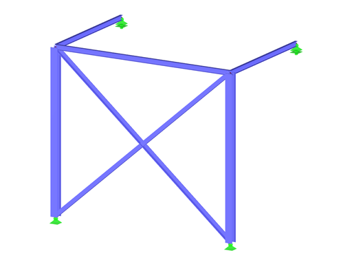
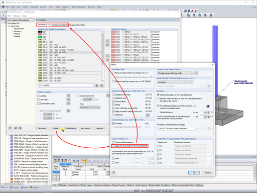
If the calculation of a member model according to the second-order analysis is terminated with an error message, this instability is often caused by the failed tension members: As soon as compression forces occur in the tension member during a calculation step, this member is no longer considered in the following iterations. Thus, the model can become instable.


.png?mw=600&hash=49b6a289915d28aa461360f7308b092631b1446e)


