How may I help you?
Do you have any questions about Dlubal products or need assistance in selecting the right one for your project?
I'm here to help. You can easily reach me through the contact options provided below.
Looking forward to hearing from you!
Amy Heilig, PE
CEO – USA Office | Sales & Technical Support Engineer


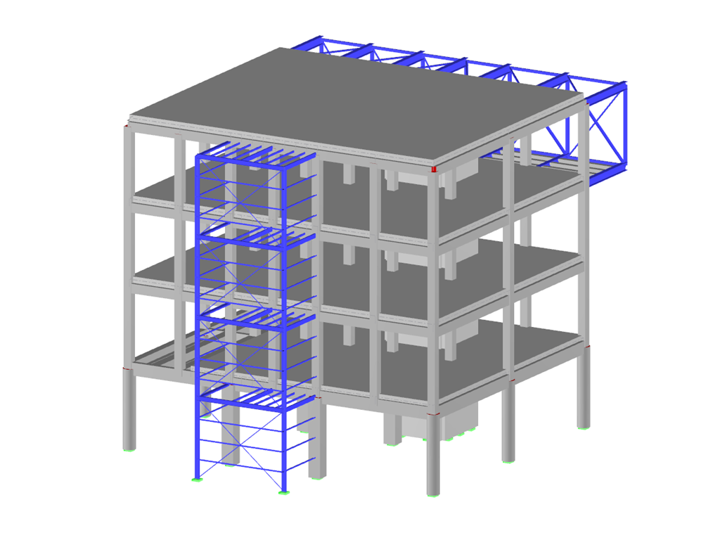
Useful Tools for Fast Generation of Structures
Total items: 10
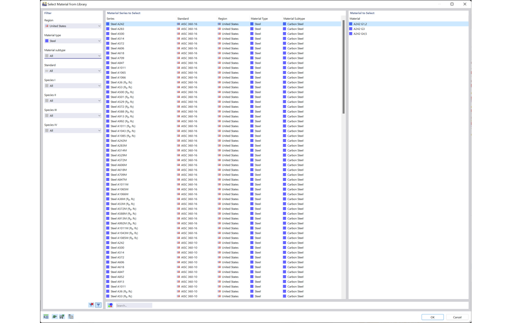
Cross-Section and Material Libraries Including Favorites
Discover the extensive cross-section and material libraries. They facilitate you the modeling of plate and beam structures. You can filter these databases and expand them with user-defined entries. You can also easily import and analyze special cross-sections from RSECTION.
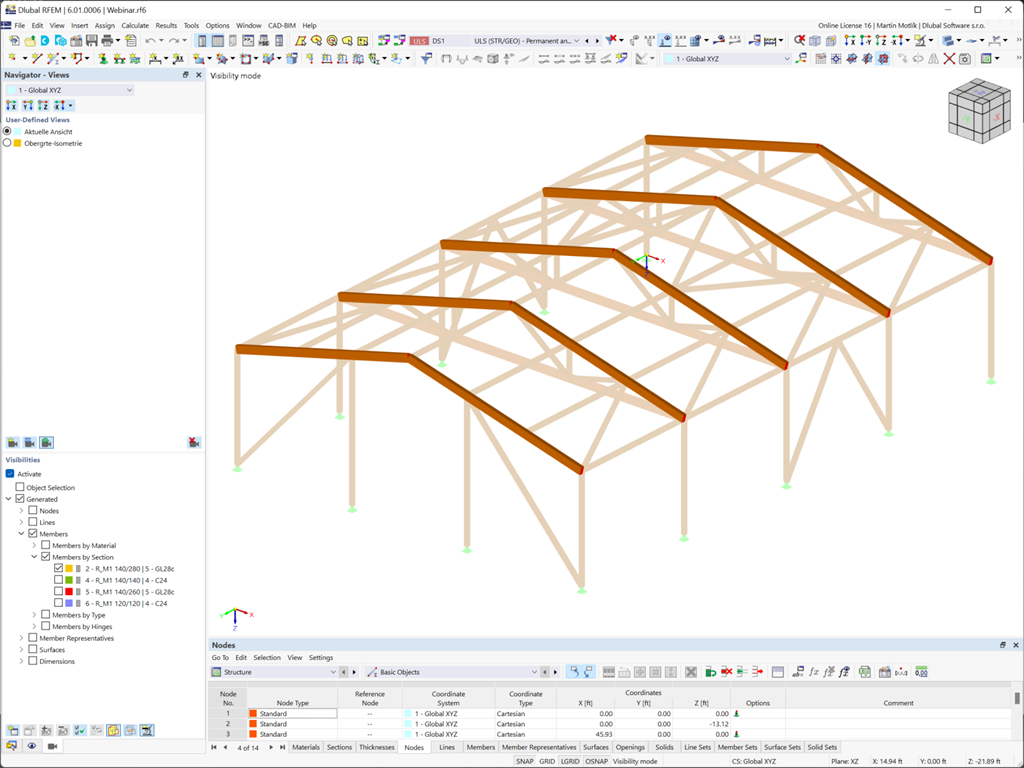
Easy Creation of Views and Visibilities
A clear display is a prerequisite for your efficient and fast work with the program. Select user-defined views from different angles to facilitate the result evaluation. Using "visibilities", you can also divide the model into user-defined and generated partial views that fulfill certain criteria. It is thus possible, for example, to activate only the surfaces of a specific material or members with a particular cross-section for the display.
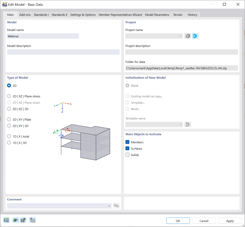
Easy Model Input
There are many options available for simple input and modeling. Your model is entered as a 1D, 2D, or 3D model. Member types such as beams, trusses, or tension members make it easier for you to define member properties. In order to model surfaces, RFEM provides you with various types, such as Standard, Without Thickness, Rigid, Membrane, and Load Distribution.
Furthermore, RFEM covers various material models, such as Isotropic | Linear Elastic, Orthotropic | Linear Elastic (Surfaces, Solids), or Isotropic | Timber | Linear Elastic (Members).
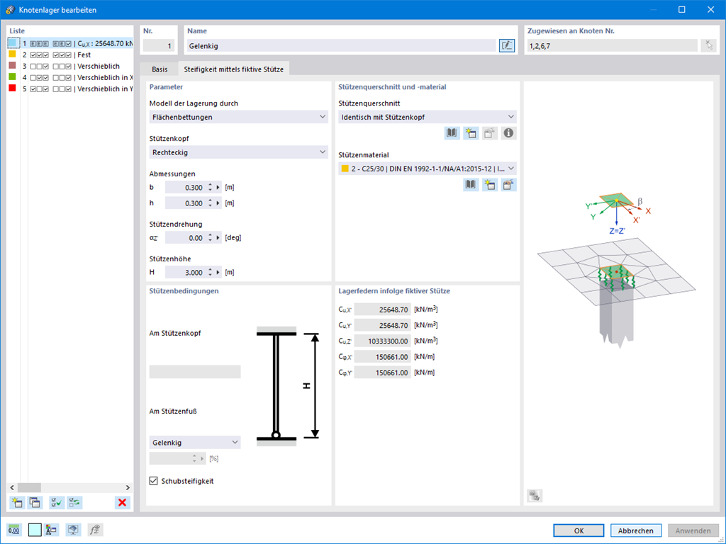
Member and Support Nonlinearities
If you are working with nonlinearities, this feature is suited very well to support you. For example, you can specify nonlinearities of member end releases (yielding, tearing, slippage, and so on) and supports (including friction). Furthermore, you can use special dialog boxes to determine the spring stiffnesses of columns and walls based on the geometry specifications.
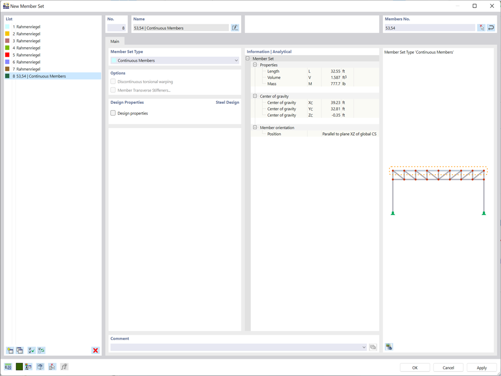
Variable Member and Surface Properties
Planning with members is also facilitated in the programs due to specific features. You can arrange members eccentrically, support them by elastic foundations, or define them as rigid links. Member sets allow you to easily apply the load on several members.
In RFEM, you can also define eccentricities of surfaces. Here, you can transform nodal and linear loads into surface loads. If necessary, divide surfaces into surface components and members into surfaces.
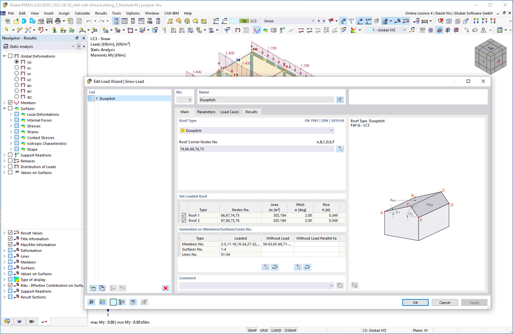
Generation of Wind and Snow Loads According to Eurocode
Do you want your structures to remain upright even in wind and snow? Then rely on the load wizards for plate and frame structures. You can now generate wind loads according to EN 1991‑1‑4 and snow loads according to EN 1991‑1‑3 (as well as other international standards). The load cases are generated depending on the roof shape.
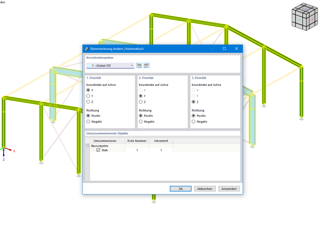
Optional Automatic Renumbering of Objects
This feature helps you stay flexible in your planning. You can subsequently adjust the numbering of structural objects, such as nodes and members. In this case, it is possible to renumber the objects automatically in accordance with the selected priorities (axis directions).
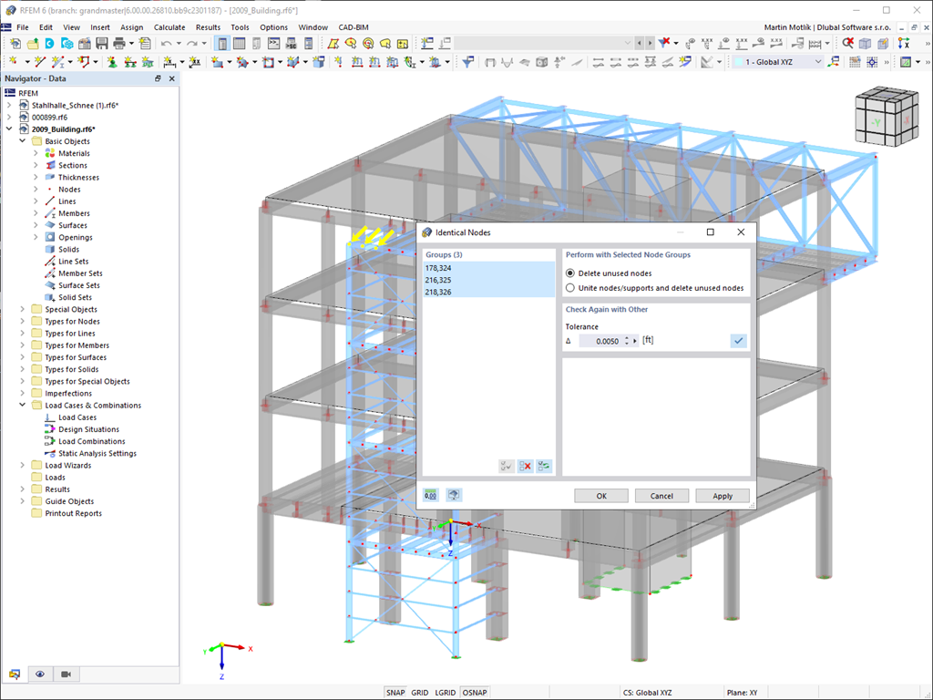

Simple Model Check
Always keep track of your model. The model check quickly detects for you the input errors, such as overlapping members or identical nodes. You can automatically connect intersecting members during your input. Members can also be extended or divided graphically. The measure function allows you to determine lengths and angles of members and surfaces (only RFEM).
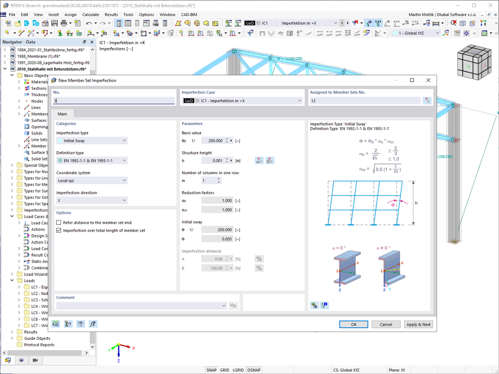
Various Load Types
If you work with loads, find a selection of useful features here. Various load types are available to you for member and surface loads (force, moment, temperature, precamber, and so on). You can assign mmber loads to members, member sets, and member lists. In the case of imperfections, inclination and precamber can be determined precisely according to the Eurocode, the American standard ANSI/AISC 360, the Canadian standard CSA S16, and so on.
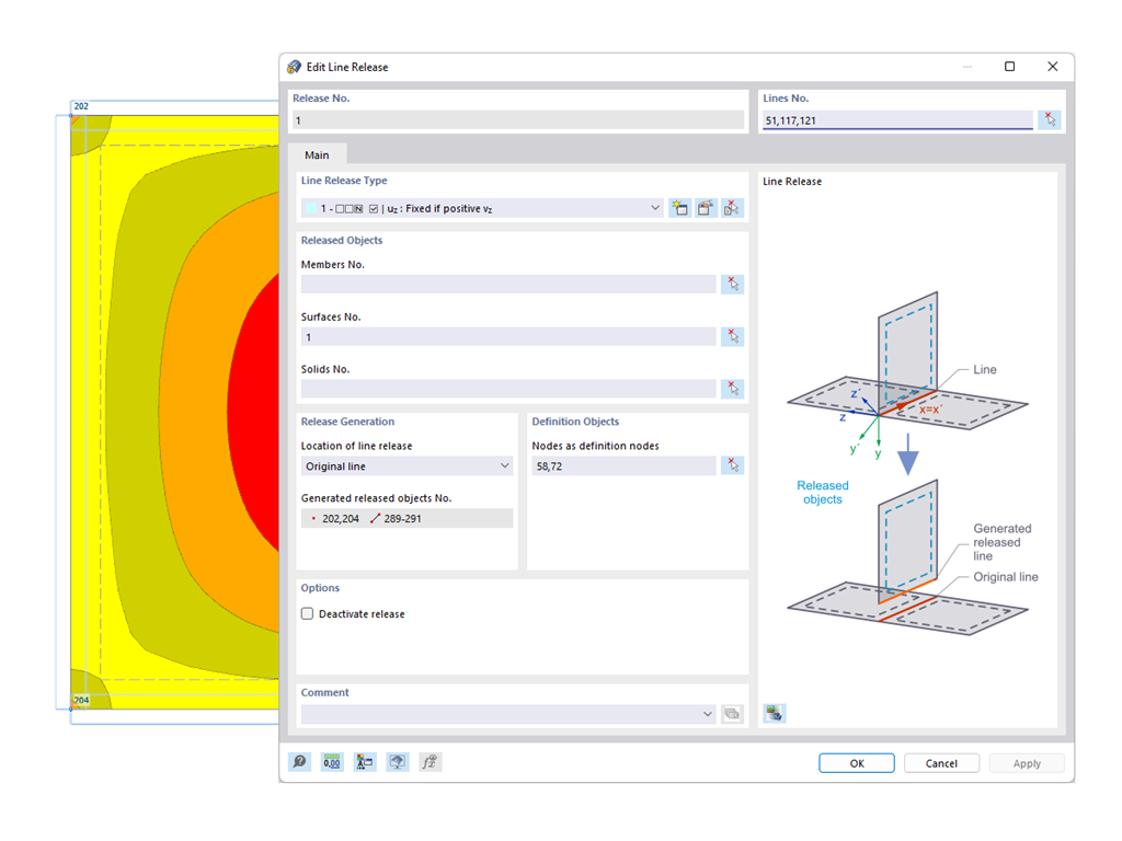
Node, Line, and Surface Releases
You probably already know that node, line, and surface releases are used to define transfer conditions between objects. For example, you can release members, surfaces, and solids from a line. It is also easily possible for the releases to have nonlinear properties, such as "Fixed if positive n", "Fixed if negative n", and so on.
Calculate Your Price

Total Amount 2,910.00 USD
The price is valid for United States.


Length: 00:01:18 min

Length: 00:00:34 min

Length: 00:00:42 min

Length: 01:06:40 min

Length: 00:02:14 min

Length: 00:00:34 min

Length: 00:00:41 min

Length: 00:24:11 min

Length: 00:01:52 min


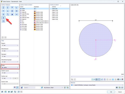
In this article, you will learn how to model and design cable structures in RFEM 6 or RSTAB 9.

This article describes and explains the influence of bending stiffness of cables on their internal forces. Furthermore, the text provides information on how this influence can be reduced.
To evaluate whether it is also necessary to consider the second-order analysis in a dynamic calculation, the sensitivity coefficient of interstory drift θ is provided in EN 1998‑1, Sections 2.2.2 and 4.4.2.2. It can be calculated and analyzed using RFEM 6 and RSTAB 9.
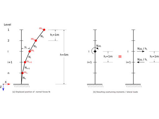
For the ultimate limit state design, EN 1998‑1, Sections 2.2.2 and 4.4.2.2 require a calculation considering the second‑order theory (P‑Δ effect). This effect may be neglected only if the interstory drift sensitivity coefficient θ is less than 0.1.


In the Navigator – Results, you can select the design situations for which you want to display the add-on results graphically.

You can add dynamic shadows in the rendering mode. In the shortcut menu, you can use sliders to change the main light position.

The material library of RFEM and RSTAB includes the timber materials according to the American standard ANSI/AWC NDS‑2024.

In addition to JavaScript, the Python high-level functions are also available in the console. Using the Python option, the console also provides you with the Python HLF functions known from the WebService function catalog for further use in the object properties dialog box for in-app scripting.
How can I change the units of result values?
How can I automatically unify two points that are close to each other?
Is it possible to define one or more nodes on one or more members automatically?
I would like to use my account for RFEM 6 / RSTAB 9, but apparently I'm not authorized to do so. Is there any way to allow this?
I would like to calculate my structure according to the second-order analysis and for this, I have created several load cases, including imperfection load cases. Do I have to combine the load cases in load combinations or result combinations?
How is it possible to consider snow and wind loads with short-time actions according to NBN EN 1990?


