Holes in Steel Members
How can I consider holes in steel members?
Answer:
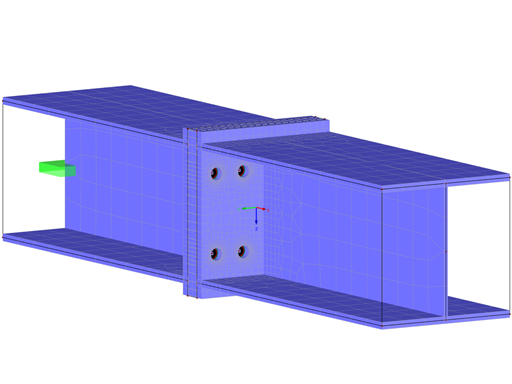
For the calculation of members, it is possible to define the cross-sections in RFEM and RSTAB that create a member with the openings arranged regularly (circular or honeycombed).If you want to place a single hole in a steel beam, you can use the "Generate Surfaces from Member" tool and put the hole as a circular opening into the web surface.
Do you have any questions?
Designing rigid end plate connections is difficult for four-row connection geometries and multi-axis bending stresses, because there are no official design methods.
The European standard EN 1993-1-8, Section 4.5.3.3. provides the user with a simplified method for the ultimate limit state design of fillet welds. According to the standard, the design is fulfilled if the design value of the resultant acting on the fillet weld area is smaller than the design value of the weld's load-bearing capacity. Thus, if you want to dimension the weld for a surface model, you will be faced with a variety of results due to the nature of FEM calculations. Therefore, we show in the following text how to determine the force components from the model.
The deformations of the FE nodes are always the first result of an FE calculation. It is possible to calculate strains, internal forces, and stresses based on these deformations and the stiffness of the elements.
The definition of the non-linear contact problem plays an important role for more detailed investigations of shear/hole bearing connections or their immediate environment. This article uses a solid model to search for comparable and simplified surface models.
In the ultimate configuration of the steel joint design, you have the option to modify the limit plastic strain for welds.
Using the "Base Plate" component, you can design base plate connections with cast-in anchors. In addition to plates and welds, the design analyzes the anchorage and the steel-concrete interaction.
In the "Edit Section" dialog box, you can display the buckling shapes of the Finite Strip Method (FSM) as a 3D graphic.
- Design of five types of seismic force-resisting systems (SFRS) includes Special Moment Frame (SMF), Intermediate Moment Frame (IMF), Ordinary Moment Frame (OMF), Ordinary Concentrically Braced Frame (OCBF), and Special Concentrically Braced Frame (SCBF)
- Ductility check of the width-to thickness ratios for webs and flanges
- Calculation of the required strength and stiffness for stability bracing of beams
- Calculation of the maximum spacing for stability bracing of beams
- Calculation of the required strength at hinge locations for stability bracing of beams
- Calculation of the column required strength with the option to neglect all bending moments, shear, and torsion for overstrength limit state
- Design check of column and brace slenderness ratios
Recommended Products for You