In this case, it is necessary to change the cross-section to TO 120/40/5/5/5/5.
Question
I get an implausible result with the expression "1.#J" in the RF‑/ALUMINUM add-on module.
How can I fix this?
Answer:
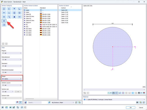
This kind of result may occur if the limit internal forces of the cross-section cannot be determined. In most cases, the problem lies in a wrongly defined cross-section or in the selection of an unsupported cross-section. Please check whether you have selected the cross-section allowed for the aluminum structure in the add-on module. These include the rolled cross-sections and parametric thin-walled cross-sections.The cross-section HK 120/40/5/5/5/5 shown in Image 01 is not a valid cross-section, as it has been selected from the area of solid cross-sections (concrete components).
In this case, it is necessary to change the cross-section to TO 120/40/5/5/5/5.
Please note that when performing a design in RF‑/ALUMINUM, you have to select a material that also covers the material thicknesses used for the cross-sections. A material that is only allowed up to t=3 mm cannot be used for a cross-section with t=5 mm.
Do you have any questions?
In this article, you will learn how to model and design cable structures in RFEM 6 or RSTAB 9.
This article describes and explains the influence of bending stiffness of cables on their internal forces. Furthermore, the text provides information on how this influence can be reduced.
The ASCE 7-22 Standard [1], Sect. 12.9.1.6 specifies when P-delta effects should be considered when running a modal response spectrum analysis for seismic design. In the NBC 2020 [2], Sent. 4.1.8.3.8.c gives only a short requirement that sway effects due to the interaction of gravity loads with the deformed structure should be considered. Therefore, there may be situations where second-order effects, also known as P-delta, must be considered when carrying out a seismic analysis.
This article presents the basic concepts in structural dynamics and their role in the seismic design of structures. Great emphasis is given to explaining the technical aspects in an understandable way, so that readers without deep technical knowledge can gain an insight into the subject.
In RFEM and RSTAB, you can visualize the flow field quantities of pressure, velocity, turbulence kinetic energy, and turbulence dissipation rate for the wind simulation.
The clipping planes are aligned with the respective wind direction.
In the ultimate configuration of the steel joint design, you have the option to modify the limit plastic strain for welds.
With the "Base Plate" component, you design base plate connections with cast-in anchors. Dabei werden Platten, Schweißnähte, Verankerung und Stahl-Beton-Interaktion analysiert.
In RFEM, you can generate surfaces from members with the library cross-sections as well as from the members with the RSECTION cross-section.
How can I fix this?
Recommended Products for You