Answer:
The most common causes are listed below:
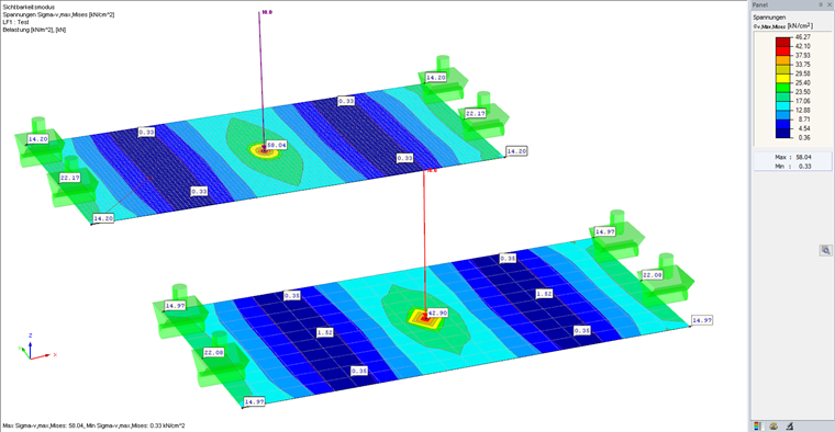
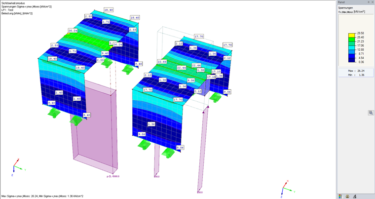
1. Singularities
Singularities occur in a limited area due to the concentration of stress-dependent result values. They are conditioned by the FEM methodology: In theory, the stiffness and/or the stress in an infinite size will concentrate on an infinitesimally small area. Therefore, singularities occur especially at point supports, load application locations, reentrant corners, or in the area of stiffness peaks.
If the result value of the stress peak is greater and the area of this stress peak is smaller in the case of a finer FE mesh, a singularity is very likely to occur.
The recommendations for dealing with the singularity locations are included in the following technical articles of our Knowledge Base; for example:
2. Unrealistic Support Definition
Rigid supports (infinitely stiff supports) are rather unrealistic in many cases. Therefore, we recommend displaying the supports as elastic supports. In this case, the stiffness of the adjacent structural components should be estimated realistically.
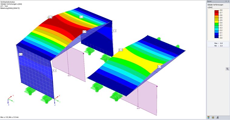
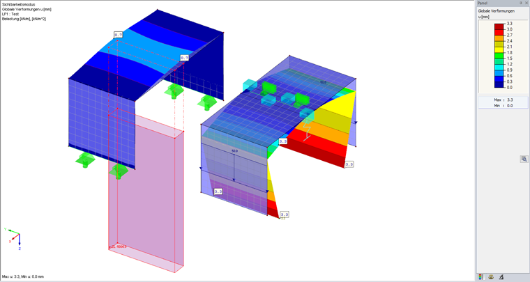
For checking purposes, the deformation diagram is suitable, possibly with a stronger precamber, as well as the result display of the support reactions or contact stresses. For a better overview, the simplest possible loads should be used for the check.
3. Incorrect Direction Definition / Incorrectly Defined Nonlinearities
A mistake in the direction definition, for example, of loads, member hinges, or line and surface releases, is often the cause of unrealistic behavior. When using local or rotated coordinate systems as reference systems, you must pay attention to the correct definition. For example, nonlinearities defined in the opposite direction are typical for supports that fail due to tension or compression.
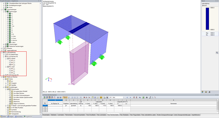
Incorrectly defined loads can be identified easily by displaying the loading. The loads applied for the calculation can be displayed easily in the Results navigator using the "Load Distribution" option.
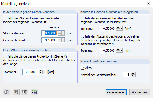
Furthermore, modeling inaccuracies can also lead to the incorrect definition of directions. By importing a DXF file, you can introduce inaccuracies into the model; for example, nodes that are not on top of each other or lines skewed in the wrong directions.
The "Regenerate Model" feature is very helpful for treating minor inaccuracies.
Incorrectly defined releases and hinges can usually be identified by means of the deformation image and the diagrams of internal forces. Again, we recommend working with simple loads for checking purposes.
4. Model does not correspond to reality
It can often happen that not all external or internal influences from a structure to be modeled have been considered sufficiently and accurately in the model. Supports or supporting structural components may not have been modeled, or they are in the wrong place. The realistic estimation of the stiffness of the adjacent structural components is also important. Provided that it has been over- or underestimated, the load transfer in the model is sometimes changed significantly.
However, it is possible to simply check the deformation, possibly by using a stronger precamber.
The following questions may help you to find the solution if the real structure is known: Is the magnitude of the deformations close to reality? Is the deformation diagram qualitatively consistent with my expectations?
A good example is presented in the following Knowledge Base article:


.png?mw=600&hash=49b6a289915d28aa461360f7308b092631b1446e)


