Introduction
The fatigue design of reinforced concrete components is based on an explicit fatigue design (Design Level 3). This design has a high accuracy, but as a result, requires a large amount of computational effort. Therefore, two simplified design methods have been developed to keep the computation time low. There are Design Level 1, which defines the maximum allowable stress range, and Design Level 2, which performs a simplified fatigue design with damage equivalent stresses.
In RFEM 6, Design Level 1 and Design Level 2 are implemented.
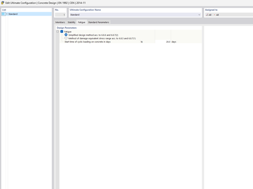
Design Level 1 = Simplified Method

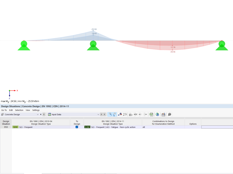
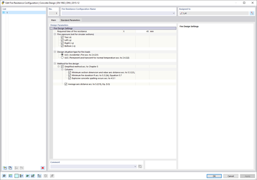
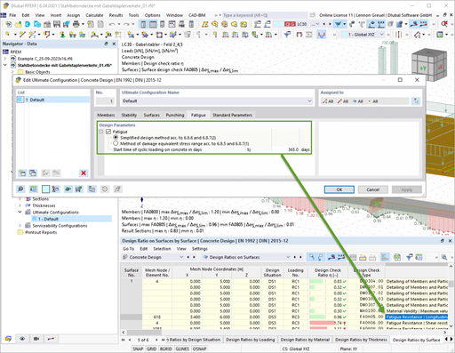
For this design, the basic combination of the acyclic actions according to Eq. 6.67, EN 1992-1-1 is required. It corresponds to the "SLS - Frequent" action combination in accordance with Eq. 6.15 according to EN 1990).
In the case of longitudinal reinforcement design, the maximum steel stress range must not exceed the stress range value specified in the standard. The loads from bending and axial force, as well as an interaction of torsion, bending, axial force, and shear, are each designed. Here, ΔσS,max is the maximum steel stress range, and k1 is the factor for the allowed stress range.
The shear design is performed with and without reinforcement. For the design check without shear reinforcement, it is necessary to meet the following condition.
In the case of a design with shear reinforcement, the shear force stress range must not exceed the stress range specified in the standard.
The design checks for the concrete compressive stress and the concrete compression struts need to meet the following condition. For the design check of the concrete compression struts, fcd,fat is reduced by the factor ν1 for shear cracks. The concrete compressive stresses are determined from the bending and axial forces, and the concrete strut stresses from the shear and torsional forces.
Design Level 2 = Method of Damage Equivalent Stress Range
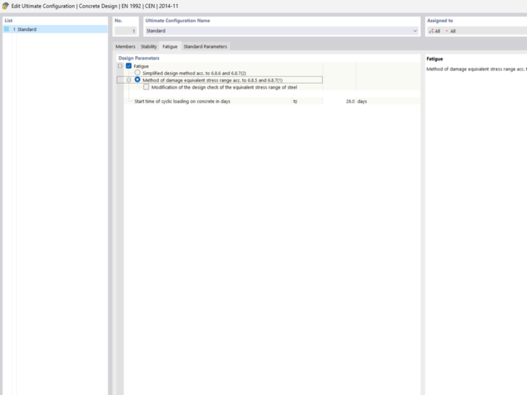
For this design check, it is necessary to combine the cyclic action with the unfavorable basic combination according to Eq. 6.69 in EN 1992-1-1.
- The following design check must be fulfilled for the longitudinal reinforcement. The loads from bending and axial force, as well as an interaction of torsion, bending, axial force, and shear, are each designed.
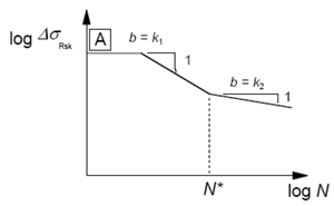
The damage equivalent stress ranges for the N* load cycles must be smaller than the allowable stress ranges for the N* load cycles according to the S-N curves.
The shear design is performed with and without reinforcement. For the design check without shear reinforcement, it is necessary to meet the following condition.
In the case of the design check with shear reinforcement, the shear force stress range must not exceed the damage equivalent stress ranges according to the S-N curve specified in the standard.
The design checks for the concrete compressive stress and the concrete compression struts need to meet the following condition.
The concrete compressive stresses are determined from the bending and axial forces, and the concrete strut stresses from the shear and torsional forces.
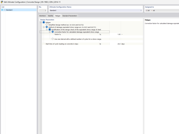
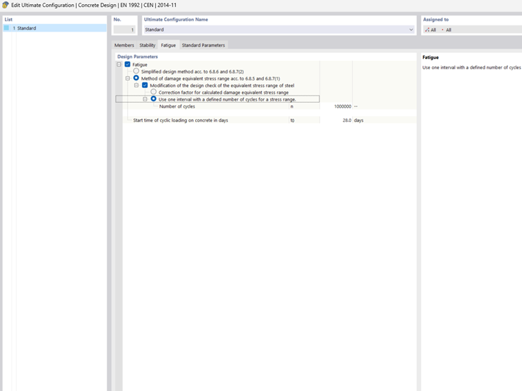
Modification of Damage Equivalent Stress Range Method
In the design configurations, you can manually adjust the following parameters. They affect the stress ranges.
- Correction factor λs
This damage equivalent factor for fatigue is based on the bridge construction according to EN 1992-2, NN.2.1, and NN.3.1. The factor increases the load-acting stress range. This factor takes into account the traffic volume, service life, and span of the supporting elements, as well as the number of lanes, traffic type, and surface roughness.
- Specification of load cycles
The number of cycles has an influence on the allowable characteristic stress ranges according to the S-N curves in compliance with Table 6.3N.
Summary
The fatigue design allows you to consider the stress differences due to load changes and the material-weakening effects due to the high number of loads. With both design methods mentioned above, two options for a simplified fatigue design are available.
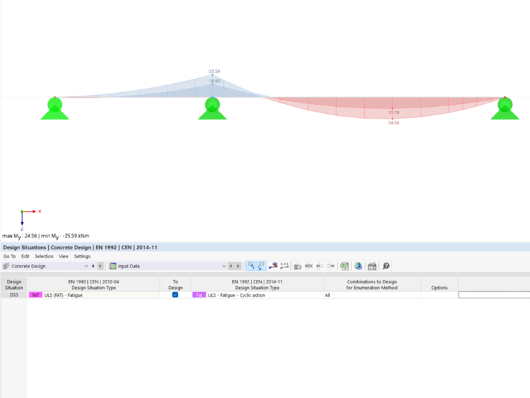
Note
The fatigue design check is performed by means of the extreme values of one or more result combinations. Thus, at least one result combination must be created for the calculation.


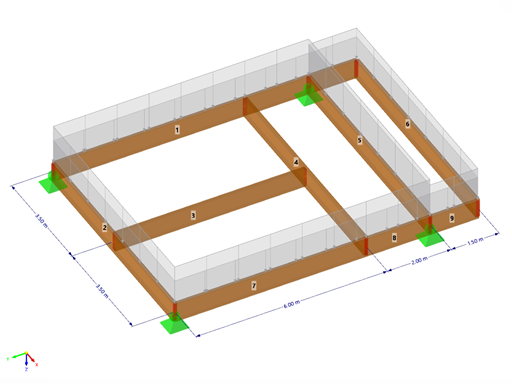
![Spans Based on Figure 5.2 from [1]](/en/webimage/039540/3493372/01_Abmessungen_EN.png?mw=512&hash=3cc425f1463bd5981b358d5889e3109e07ae1233)