Answer:
In contrast to the normal surface or nodal load, a free load is defined by the influence range and the influenced elements. By definition, free loading is only applied to the areas of the selected elements resting within this influence range.

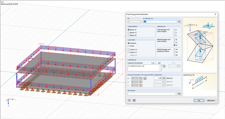
A free load is defined by the absolute coordinates, with no regard to the elements of the model. For entering data, you can easily define them by selecting the model nodes, though there will be no link to the selected nodes. For example, if the model is then moved, the free load remains in the assigned position.
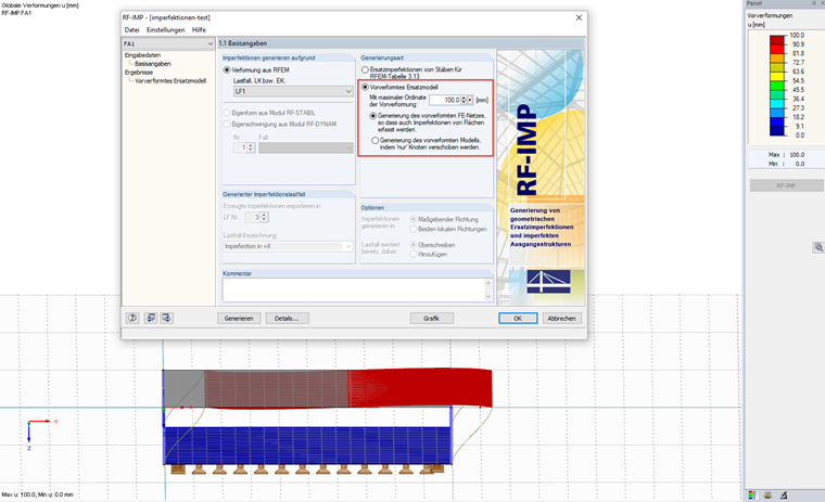
When using an imperfection generated by RF‑IMP as a pre‑deformed FE mesh, the free loads are applied to this deformed structure. This may be out of the influence range and absorbs no load.
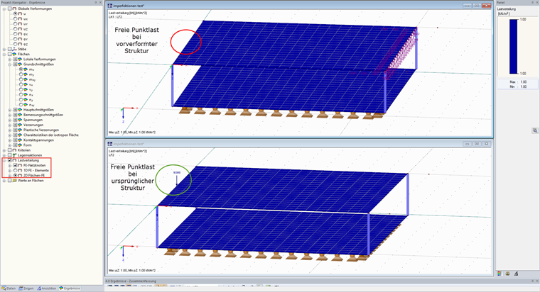
If the load is expected to be linked to the structure and also moved in the case of displacements and generated imperfections, it is necessary to use the standard loads. Alternatively, the area of influence of the free load can be increased as required in order to, nevertheless, apply loads to the entire structure.
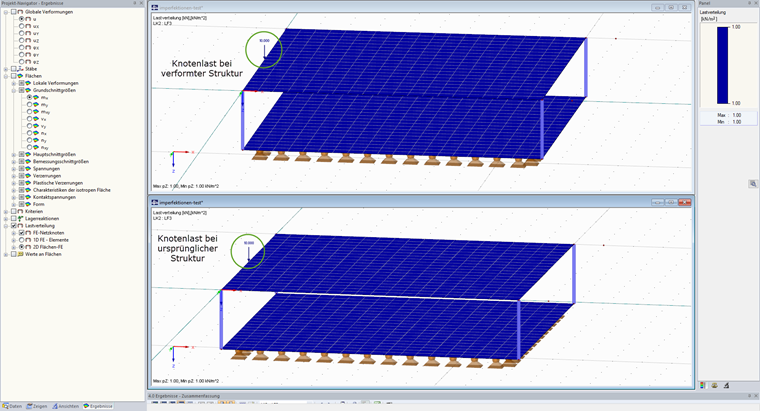
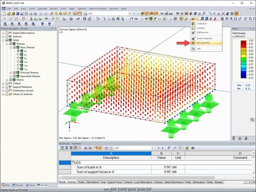
You can simply check the applied load by displaying the load distribution in Project Navigator - Results.


Dlubal_KohlA_]_LI.jpg?mw=350&hash=ee8d38f1c4853d80307fa156c159b5e78a3fdca9)


Dlubal_KohlA_]_LI.jpg?mw=350&hash=21d94ec9a723c608496e9e95a21bb1309ab5067a)
www.isen_LI.jpg?mw=350&hash=884ca7c4739fd5d2643994f417a345f17b1e1fad)


.jpg?mw=350&hash=91f398b559b26a6ac36fd7ecdf5e395e7b9b856d)


.png?mw=600&hash=49b6a289915d28aa461360f7308b092631b1446e)


