In general, Eq. 6.31 provides the following design criterion for cross‑sections of Class 1 to Class 2:
MEd < MN,Rd
The calculation of MN,Rd is specified in Sec. 6.2.9.1 (Eq. 6.32 trough Eq. 6.40) for the following cross‑sections:
- Solid sections (rectangular)
- I- and H-sections (doubly symmetrical)
- Hollow sections (circular and rectangular)
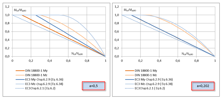
For doubly symmetrical I- and H-sections subjected to bending about the major axis, Eq. 6.36 applies:
Thus, two initial values are included in the calculation:
The standard sets a limit for α at 0.5, and the lowest value of rolled cross‑sections is about 0.2. A graphical evaluation of the interaction according to EN 1993‑1‑1 [1] and DIN 18800 shows almost the same results for the small α.
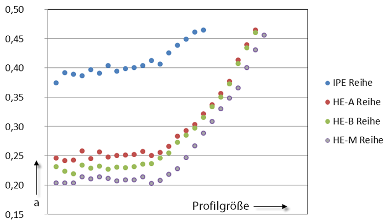
The efficiency of the plastic design of cross-sections depends mainly on the cross-section parameter α. The evaluation of the current cross-section series gives the following distribution.
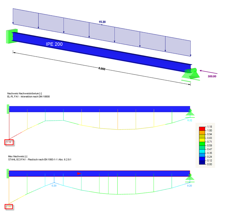
This situation can be explained on a simple example. as you can see, a significantly higher load (pure cross-section design without stability analysis) can be reached when using the cross-section IPE 200 according to EN 1993‑1‑1 than according to DIN 18800.


.jpg?mw=350&hash=91f398b559b26a6ac36fd7ecdf5e395e7b9b856d)


.png?mw=600&hash=49b6a289915d28aa461360f7308b092631b1446e)


