Creating a validation example for Computational Fluid Dynamics (CFD) simulations in wind engineering applications involves several specific steps tailored to the complexities of wind flow and its interactions with structures and environments. Here's a step-by-step guide:
1. Define the Wind Engineering Problem
- Clearly specify the wind engineering scenario you are simulating, such as wind flow around buildings, bridges, or other structures.
- Include details about the terrain, atmospheric boundary layer characteristics, and any relevant environmental factors.
2. Select an Appropriate Benchmark Case
- Choose a well-documented wind engineering case study with reliable experimental or field data. This could be wind tunnel tests or full-scale measurements.
- The case should closely resemble your scenario in terms of geometry, scale, and wind conditions.
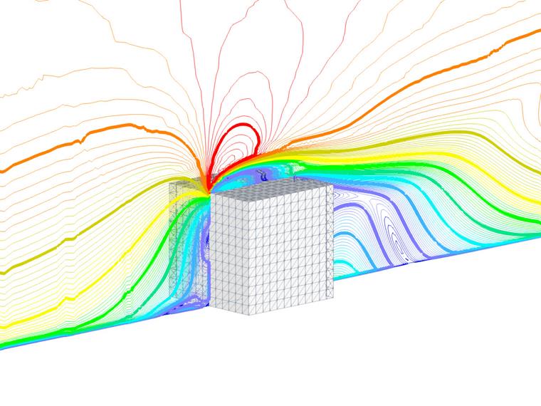
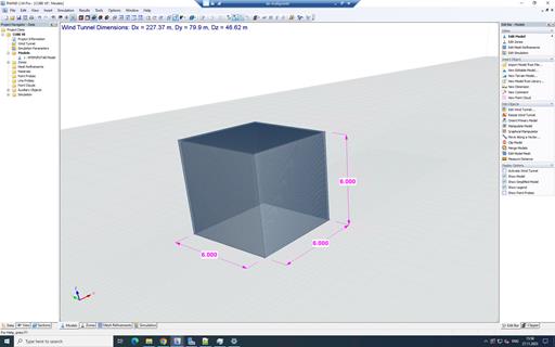
For our current study, the scientific paper [1] from Journal of Wind Engineering is chosen as benchmark case. The model is shown in Figure 1:
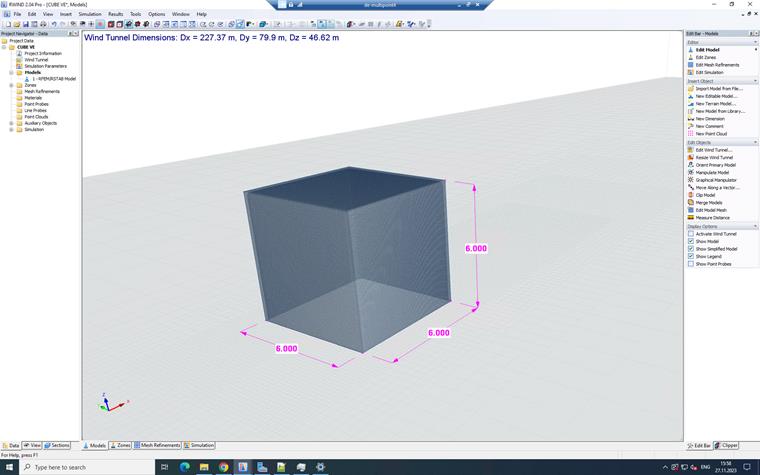
3. Develop the CFD Model
- Geometry: Create a digital model of the structure and surrounding terrain. For buildings, include details like the shape, facade features, and nearby structures.
- Meshing: Generate a mesh that captures the geometry accurately, paying special attention to areas where high flow gradients are expected, such as corners and edges of structures.
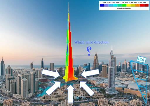
- Boundary and Initial Conditions: Set boundary conditions that reflect the wind profile (speed and direction) at different heights, temperature variations, and pressure conditions.
- Solver Settings: Select suitable solvers and turbulence models (such as k-ε or Large Eddy Simulation) that are known to perform well in wind engineering simulations.
The initial assumptions are considered as Table 1.
| Table 1: Dimensional Ratio and Input Data | |||
| Basic Wind Velocity | V | 10.13 | m/s |
| Mean Roof Height | h | 6 | m |
| Horizontal Dimension (Edge Distance) | α | 6 | m |
| Roof Angle | θroof | 0 | Degree |
| Air Density - RWIND | ρ | 1.25 | kg/m3 |
| Wind Directions | θwind | 0 | Degree |
| Turbulence Model - RWIND | Steady-State RANS k-ω SST | - | - |
| Kinematic Viscosity (Equation 7.15, EN 1991-1-4) - RWIND | ν | 1.5*10-5 | m2/s |
| Scheme Order - RWIND | First and Second | - | - |
| Residual Target Value - RWIND | 10-4 | - | - |
| Residual Type - RWIND | Pressure | - | - |
| Minimum Number of Iterations - RWIND | 800 | - | - |
| Boundary Layer - RWIND | NL | 10 | - |
| Type of Wall Function - RWIND | Enhanced / Blended | - | - |
4. Run the Simulation
- Conduct simulations considering both steady-state and transient analyses, as wind flow can have significant temporal variations.
- Ensure that the simulation runs long enough to capture the relevant flow dynamics around the structures.
5. Validation Process
- Compare with Benchmark Data: Contrast your simulation results with the benchmark case data, focusing on parameters like wind speed profiles, pressure distribution on structures, and turbulence intensity.
- Error Analysis: Perform quantitative analysis to assess discrepancies between your simulation and the benchmark data.
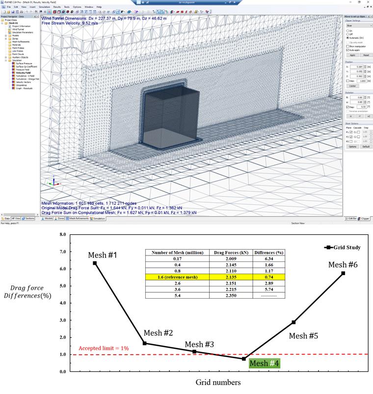
- Sensitivity Analysis: Test how changes in mesh density, boundary conditions, and turbulence models affect your results.
For the current example, the sensitivity analyse is showed according to Figure 2. The results of total drag forces is investigated for four different mesh. The mesh independency is obtain at 1.6 million cells.
6. Documentation
- Thoroughly document your methodology, including the assumptions, boundary conditions, and all relevant settings.
- Include a detailed comparison of your results with the benchmark data, highlighting both agreements and discrepancies.
7. Iterative Refinement
- If there are significant deviations from the benchmark data, refine your model. This might involve adjusting mesh resolution, modifying turbulence models, or revising boundary conditions.
- Repeat the simulation and validation process until the model reliably predicts wind flow behavior.
8. Considerations for Wind Engineering Applications
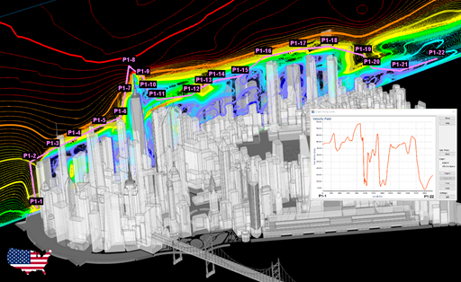
- Wind engineering CFD simulations often need to account for complex phenomena such as vortex shedding, buffeting, and wake effects.
- Urban topology, terrain effects, and atmospheric stability conditions can significantly influence the wind flow and should be included in the model when relevant.
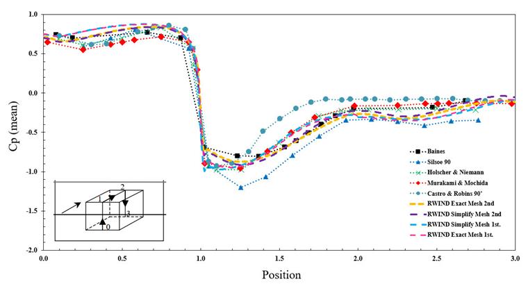
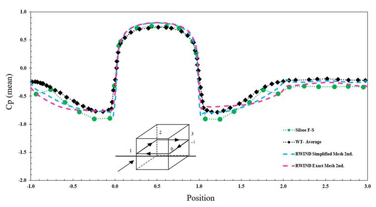
9. Results
The diagram of average Cp value using steady simulation is performed for simplified and exact mesh generation method in RWIND and also first and the second method of numerical scheme. The results shows good agreement between experimental and numerical method regarding reference [1]. Figure 3 and Figure 4 show average Cp value through specified line in vertical and horizontal direction.
10. Conclusion
This validation process is crucial for ensuring that your CFD model accurately represents the complexities of wind flow in engineering applications. It helps in building confidence in the simulation results, which can then be used for design decisions, safety assessments, or further research studies. The validation model is available here for download: