27 Results
View Results:
Sort by:

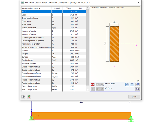
Using the Timber Design add-on, timber column design is possible according to the 2018 NDS standard ASD method. Accurately calculating timber member compressive capacity and adjustment factors is important for safety considerations and design. The following article will verify the maximum critical buckling strength calculated by the Timber Design add-on using step-by-step analytical equations as per the NDS 2018 standard including the compressive adjustment factors, adjusted compressive design value, and final design ratio.

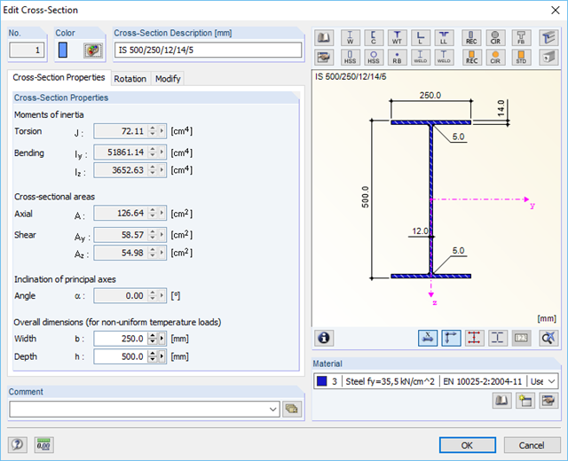
Plate girder is an economical choice for long spans construction. I-section steel plate girder typically has a deep web to maximize its shear capacity and flange separation, yet thin web to minimize the self-weight. Due to its large height-to-thickness (h/tw) ratio, transverse stiffeners may be required to stiffen the slender web.

In order to be able to carry out a pushover analysis, it is necessary to transform the determined capacity curve into a simplified form. The N2 method is described in Eurocode EN 1998. This article should help to explain what a bilinearization according to the N2 method involves.

In this article, a lap joint of a ZL purlin on a monopitch roof is modeled and designed using the Steel Joints add-on, and compared with the load-bearing capacity table of the manufacturer.

A new capability within RFEM 6 when designing concrete columns is being able to generate the moment interaction diagram according to the ACI 318-19 [1]. When designing reinforced concrete members, the moment interaction diagram is an essential tool. The moment interaction diagram represents the relationship between the bending moment and axial force at any given point along a reinforced member. Valuable information is shown visually like strength and how the concrete behaves under different loading conditions.

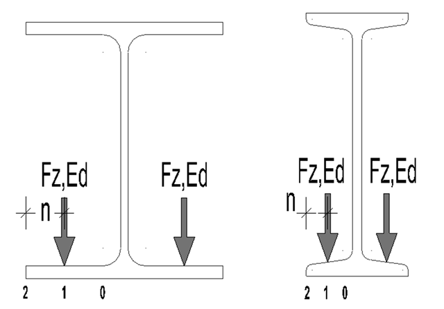
A standard scenario in timber member construction is the ability to connect smaller members by means of bearing on a larger girder member. Additionally, member end conditions may include a similar situation where the beam is bearing on a support type. In either scenario, the beam must be designed to consider the bearing capacity perpendicular to the grain according to NDS 2018 Sec. 3.10.2 and CSA O86:19 Clauses 6.5.6 and 7.5.9. In general structural design software, it is typically not possible to carry out this full design check, as the bearing area is unknown. However, in the new generation RFEM 6 and Timber Design add-on, the added 'design supports' feature now allows users to comply with the NDS and CSA bearing perpendicular to the grain design checks.

The design of cross-sections according to Eurocode 3 is based on the classification of the cross-section to be designed in terms of classes determined by the standard. The classification of cross-sections is important, since it determines the limits of resistance and rotation capacity due to local buckling of cross-section parts.

Defining the appropriate effective length is crucial in obtaining the correct member design capacity. For X-bracing that is connected at the center, engineers often wonder if the full end-to-end length of the member shall be used, or whether using half of the length to where the members are connected is sufficient. This article outlines the recommendations given by the AISC and provides an example on how to specify the effective length of the X-braces in RFEM.

The reinforced concrete design for fire situations is carried out according to the simplified method based on EN 1992-1-2, Clause 4.2. The "zone method" described in Annex B.2 is used: The cross-section is subdivided into a number of parallel zones of equal thickness, and their temperature-dependent compressive strength is determined. The reduced load-bearing capacity in the event of fire exposure is thus represented by a reduced structural component's cross-section with reduced strengths.
The network-capable Project Manager controls the projects of all Dlubal Software applications in one central location.

The RF-/LIMITS add-on module allows you to compare the ultimate limit state of members, member ends, nodes, nodal supports, and surfaces (RFEM only) by means of a defined ultimate load capacity. Furthermore, you can check nodal displacements and cross-section dimensions. In this example, the column bases of a carport are to be compared with the maximum allowable forces specified by the manufacturer.
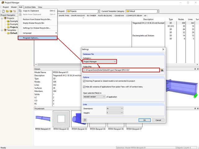
The network-capable Project Manager controls the projects of all Dlubal Software applications in one central location. The projects are linked to the folders on the hard disk.

The classification of cross-sections is intended to determine the limits of resistance and rotational capacity due to local buckling of cross-section parts. In EN 1999‑1‑1, 6.1.4.2 (1), four classes are defined.

According to Clause 6.2.2 (6) of EN 1993‑1‑8:2010‑12, you can apply friction using the friction coefficient to design the shear capacity.

The European standard EN 1993-1-8, Section 4.5.3.3. provides the user with a simplified method for the ultimate limit state design of fillet welds. According to the standard, the design is fulfilled if the design value of the resultant acting on the fillet weld area is smaller than the design value of the weld's load-bearing capacity. Thus, if you want to dimension the weld for a surface model, you will be faced with a variety of results due to the nature of FEM calculations. Therefore, we show in the following text how to determine the force components from the model.

Using the RF-TIMBER AWC module, timber column design is possible according to the 2018 NDS standard ASD method. Accurately calculating timber member compressive capacity and adjustment factors is important for safety considerations and design. The following article will verify the maximum critical buckling in RF-TIMBER AWC using step-by-step analytical equations as per the NDS 2018 standard including the compressive adjustment factors, adjusted compressive design value, and final design ratio.
Using the RF-TIMBER AWC module, timber beam design is possible according to the 2018 NDS standard ASD method. Accurately calculating timber member bending capacity and adjustment factors is important for safety considerations and design. The following article will verify the maximum critical buckling in RF-TIMBER AWC using step-by-step analytical equations as per the NDS 2018 standard, including the bending adjustment factors, adjusted bending design value, and final design ratio.
For suspension cranes, the bottom chord of the runway girder is subjected to local flange bending due to the wheel loads in addition to the main load-bearing capacity. The bottom chord behaves like a slab due to these local bending stresses, and has a biaxial stress condition [1].
A single-span beam with lateral and torsional restraint is to be designed according to the recommendations of Eurocode 3 and AISC. If the beam does not reach the required load-bearing capacity, it must be stabilized.

When designing bending-resistant connections from I-beams, the connection is dissolved into the individual parts. For these basic components of a joint, there are separate formula calculators for load-bearing capacity and stiffness. In RFEM and RSTAB, frame joints can be designed using the RF-/FRAME-JOINT Pro add-on module.
If a bending load of a brittle beam element (an unreinforced concrete beam) is increased by means of the bending capacity, the structure responds by breaking the cross-section and the member is separated into two segments. At the time of the failure, the broken part suddenly loses its potential to transfer the bending moment. Due to the segmentation, the critical part also fails to transfer the other force types, such as axial forces.
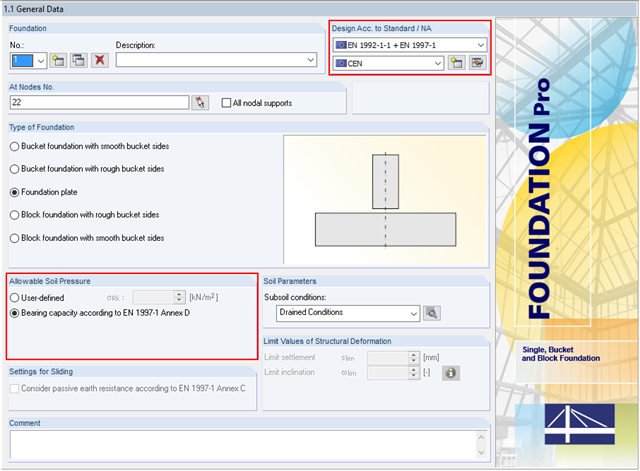
In addition to the reinforced concrete design according to EN 1992‑1‑1, RF-/FOUNDATION Pro allows you to perform geotechnical designs according to EN 1997‑1. In RF-/FOUNDATION Pro, the design of the allowable soil pressure is performed as a ground failure resistance design. If you select CEN as National Annex, you have two options for defining the ground failure resistance. First, you can directly specify the allowable characteristic value of the soil pressure σRk. Second, there is also the option to analytically determine the bearing capacity according to [1], Annex D.
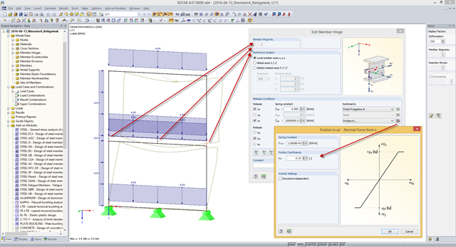
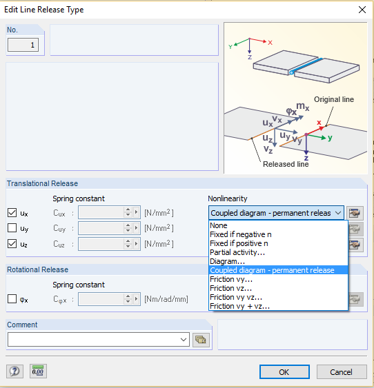
Some compound beam structures, such as stacked containers or retracted telescopic bars, transfer the forces in the connection between the components by friction. The load-bearing capacity of such a connection depends on the effective axial force perpendicular to the friction plane and on the friction coefficients between both friction surfaces. For example, the more the friction surfaces are compressed, the more horizontal shear force can be transferred by the friction surfaces (static friction).
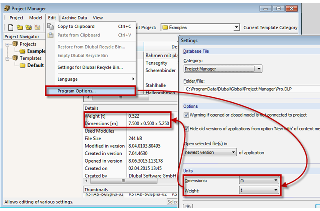
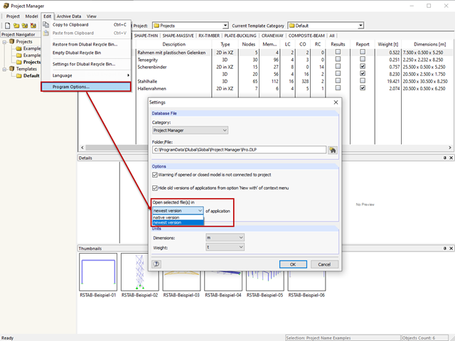
The network-capable Project Manager controls the projects of all Dlubal Software applications in one central location. A table displays the important information for each model and corresponding file. Now, you can set dimension and weight units in the program options.

Prior to the analysis of steel cross‑sections, the cross‑sections are classified according to EN 1993‑1‑1, Sec. 5.5, with respect to their resistance and rotation capacity. Thus, the individual cross-section parts are analyzed and assigned to Classes 1 to 4. The cross-section classes are determined subsequently and usually assigned to the highest class of the cross-section parts. If plastic resistance is to be applied to further design of cross-sections of Class 1 and Class 2, you can analyze the elastic resistance of cross-sections as of Class 3. In the case of cross-sections of Class 4, local buckling occurs even before reaching the elastic moment. In order to take this effect into account, you can use effective widths. This article describes the calculation of the effective cross-section properties in more detail.
The RF-/STEEL EC3 add‑on module performs a detailed cross‑section classification on each design before the design is carried out. Thus, the susceptibility to local buckling of all cross-section parts is evaluated. The defined cross-section class has an effect on the resistance and rotational capacity determination.
Modern buildings are designed with spaces tailored to personal desires and dreams, expressing individual lifestyles. These requirements often include ceilings - whether in houses, office buildings, or public buildings - that have an enormous span and no support, allowing optimal use of the space below. However, this requires a very high stability level for load‑bearing capacity and serviceability reasons. By extending the size of beam or plate cross-sections, you can increase the stability, but the cost effectiveness decreases because of the additional consumption of material. One common solution for these large spans is to use timber or steel downstand beams.