30 Results
View Results:
Sort by:

When modeling and designing glass panes in RF-GLASS, you have two different options for the FE mesh settings.

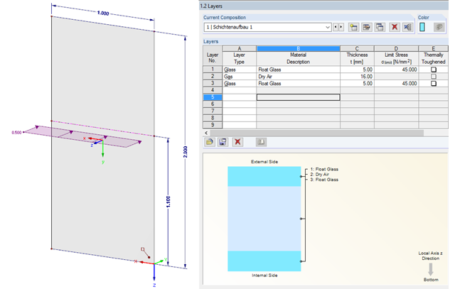
Designing vertical insulating glass requires assigning different loads on the individual layers of the entire glass unit. This occurs, for example, with simultaneous actions from wind loads and fall protection.

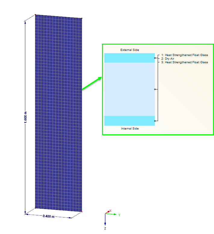
To work even more efficiently, RF‑GLASS allows you to create and save different, user‑defined layer structures that can be reimported later or loaded in another project.

The additional loads from self‑weight are usually composed of several layers; for example, classic floor and ceiling layers in buildings, or road coatings for bridge constructions. When defining load definitions in RFEM and RSTAB, you can use the multi-layer load to define the individual layers with thickness and specific weight.

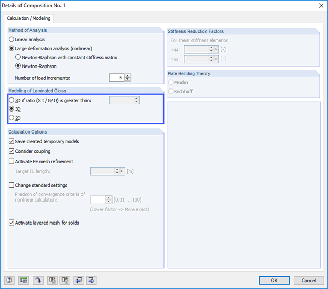
For designing glass in the RF‑GLASS add‑on module, you can use one of two calculation methods: a 2D or a 3D calculation. The main difference between these design options is the automatic modeling of the layers in a temporary model. In a 2D calculation, each layer is generated as a surface element (plate theory); in a 3D calculation, it is generated as a solid. Depending on the selected layer composition, you can either select an option or find it preselected by the program.

In the RF-GLASS add-on module, 3D rendering is implemented to facilitate the definition of the support conditions. This interactive graphical visualization facilitates the input and control of line and nodal supports. However, the schematic display can also be selected, if necessary.

DXF layers of ground plans cannot be used directly in FEA programs because only the outer contours of the elements (walls, ceilings, and so on) are available in the drawing. The FEM programs require system axes, but only the outer contours of the elements (walls, ceilings, and so on) are available in the DXF drawing.

When using the RF‑GLASS add‑on module, you can define just the geometry in the main program, as well as the load situation of the structural component to be designed. The respective support conditions and all further design-relevant definitions (for example, the layer structure and support conditions), can be further specified in RF‑GLASS.
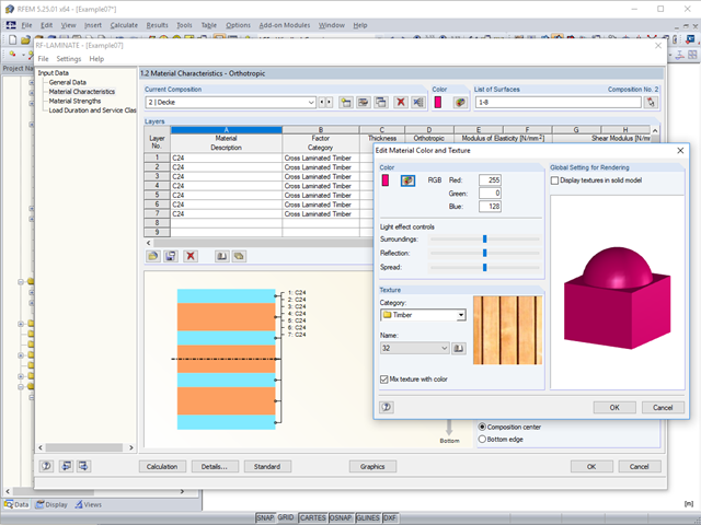
To better distinguish between the different layer compositions (for example, for walls and ceilings), you can assign user‑defined colors and textures to each composition.

Concrete on its own is characterized by its compressive strength. An important part of reinforced concrete is reinforcing steel, which contributes to both the compressive and the tension resistance of the concrete. Welded wire fabric is generally located in the tension areas of the beams or surface elements (hollow core ceiling, wall, shell) to transfer the tensile forces induced by external loading.
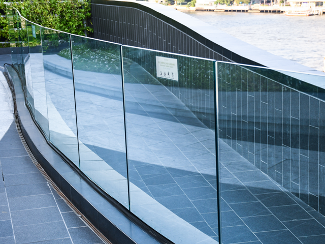
The architectural requirements for guardrails are still very high, and railings usually require a high degree of transparency. Glass railings, which do not require a visible support frame, offer a possible solution.

According to Book 631 of the DAfStb (German Committee for Structural Concrete), Chapter 2.4, the structural behavior of ceilings changes if their continuous support by walls is interrupted in areas of openings. Depending on the length of the opening area and the plate thickness, measures are necessary regarding the analysis of the ceiling in the area of the opening.
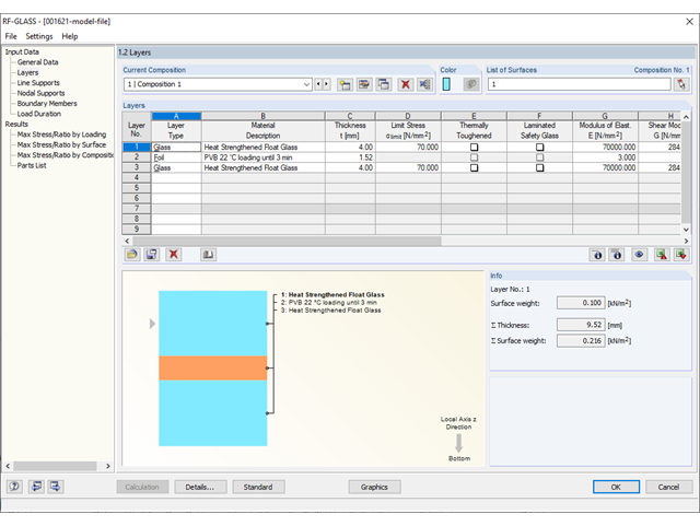
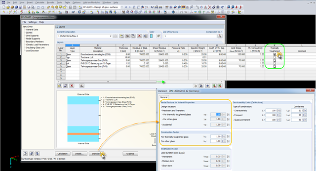
Different glass types and layer structures are available for glass structures used for different purposes. The following types are usually used: float glass, partly tempered glass, and toughened safety glass.
Due to the special properties of glass, you also have to pay close attention to the details when modeling in an FE model. Glass has a very high compressive strength and is, therefore, generally only designed for its tensile stresses. One particular disadvantage of the material is its brittleness. Stress peaks that occur in the calculation must, therefore, not be readily neglected.
Modeling planar structural components such as glass panes is generally possible only in RFEM. If it is necessary to define the stiffening effect of a pane in a particular case, it can also be simulated in RSTAB.
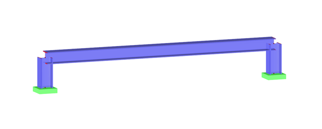
The proportion of glass used when planning a building is increasing. Open, light-flooded buildings represent the modern art of architecture. However, specialized engineers have to face new challenges during planning. One such example is ceiling-high glass facades loaded by a handrail. The influence of this loading, as well as the calculation of the deformation, are shown in this article.
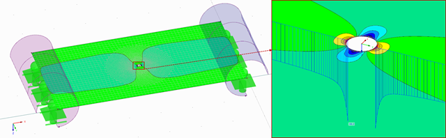
Loading panes of insulating glass due to climatic effects are clearly regulated in DIN 18008. In the case of the corresponding pane geometry, this load type can also govern for the ultimate limit state design. The FE design on the entire structure with the space between panes represented as the volume of a gas provides exact results for the analysis. However, a plausibility check is also becoming increasingly important. This article shows various options for performing these checks.
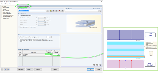
The insulating glass pane design places a special requirement on the load application point of the loading. For example, wind loads and loads due to fall protection may appear. For this, the wind load should be applied on the external glass side and the handrail load should act on the internal glass pane.
As mentioned in Part 1, according to the current standard DIN 18008-3, it is allowed in glass construction to represent point supports for glass components by means of FEM in order to design the adequate ultimate limit state. The rules are described in Annex B of the standard [1].
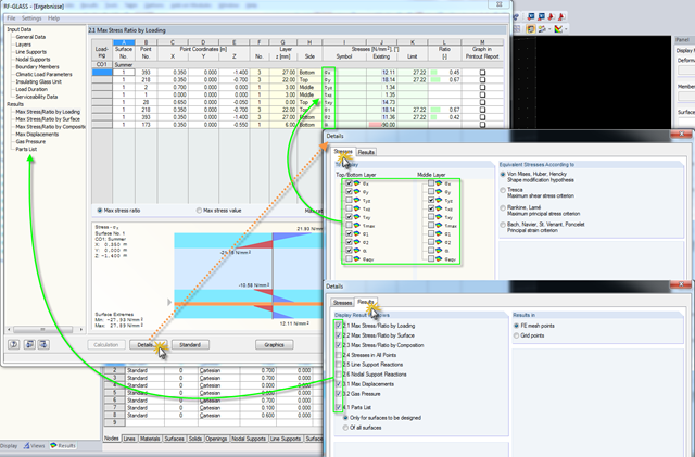
Click the [Details] button in RF-GLASS to select the results to be displayed. In order to get a better overview for the result evaluation, you can select the individual stress graphics (principal stresses, stresses oriented to axes, shear stresses) as well as various result windows. This way, you can show only the results you require.
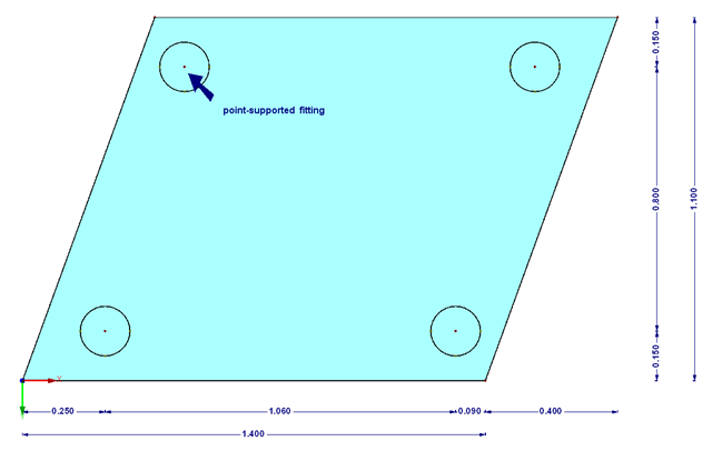
The transparency of the glass material should not be missing in any building. In addition to the typical application areas such as windows, this building material is increasingly being used for facades, canopies, or even as bracing of stairways. Of course, the planning architects often set a very high standard of transparency on fixation of the glass panes. This requires special glass fittings that couple the glass panes.
![Vibration Analysis (Source: [3])](/en/webimage/009798/467822/01-de-png.png?mw=640&hash=52805a227240ecddbd69b1d113348bf2749c3f9e)
The vibration design of cross‑laminated timber plates often governs for wide-span ceilings. The advantage of timber as a lighter material compared to concrete is turned into a disadvantage here, since a high mass is advantageous for a low natural frequency.
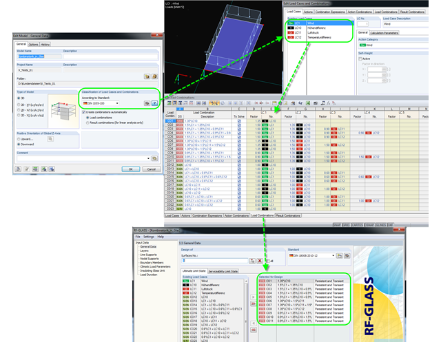
For the superposition or combination of loads, the German standard DIN 18008 refers to DIN 1055‑100. This also applies for the individual parameters of climatic loads to be transferred. In this case, it is possible to summarize the temperature change and meteorological pressure change in a single load and to define the local altitude change as a permanent load.
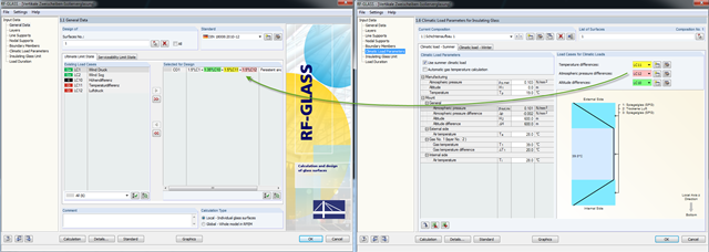
A new feature allows you to assign climatic loads to load cases when designing panes of insulating glass. Climatic loads are included in three categories here: temperature difference, atmospheric pressure difference, and altitude difference.
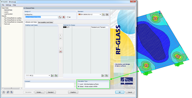
In RF-GLASS, two different calculation types are generally available in Window 1.1. There are the "Local" and the "Global" calculations.
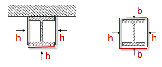
For unprotected I‑sections, the standard provides the correction factor ksh according to Equation 4.26a in Section 4.2.5.1 (2) to consider the shadowing effect. The term [Am/V]b is used there. This section factor includes Am, which represents the box enclosing the cross‑section (Index b = boxed). In the case of a three-sided fire exposure (a girder with a massive ceiling), the flange surface not exposed to fire is not taken into account when determining [Am/V]b.
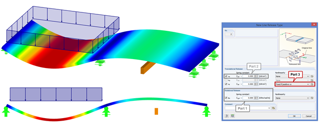
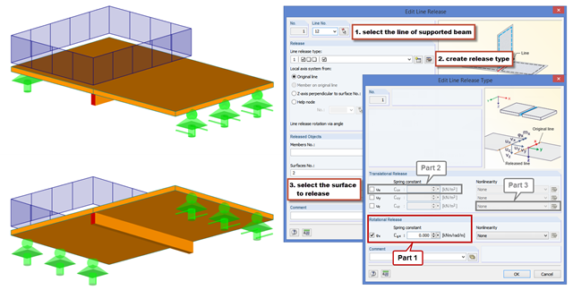
In order to increase the stiffness of a ceiling structure in case of renovation, visible downstand beams are used that are not connected to the ceiling structure. Nonlinear line releases can be used to transfer only the compression forces. If there are tensile forces between the ceiling and the downstand beam, as shown in the figure, the downstand beam does not transfer the stiffness in the overall structure.
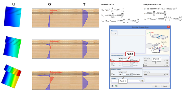
In order to represent the stiffness of the entire structure correctly, you can consider shear coupling between the ceiling and the downstand beam using the line release. This way, you can define a spring constant, thus avoiding the replacement system by using coupling members. The spring constant results from the shift modulus of the fastener, which can be determined according to EN 1995-1-1 or ANSI/AWC NDS, for example.
Modern buildings are designed with spaces tailored to personal desires and dreams, expressing individual lifestyles. These requirements often include ceilings - whether in houses, office buildings, or public buildings - that have an enormous span and no support, allowing optimal use of the space below. However, this requires a very high stability level for load‑bearing capacity and serviceability reasons. By extending the size of beam or plate cross-sections, you can increase the stability, but the cost effectiveness decreases because of the additional consumption of material. One common solution for these large spans is to use timber or steel downstand beams.