69 Results
View Results:
Sort by:

This article describes and explains the influence of bending stiffness of cables on their internal forces. Furthermore, the text provides information on how this influence can be reduced.
![Spans Based on Figure 5.2 from [1]](/en/webimage/039540/3493372/01_Abmessungen_EN.png?mw=640&hash=a3c436931baff3514db261b2d11bfa39abae9170)
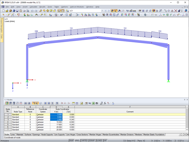
In order to correctly design a downstand beam or a T-beam in RFEM 6 using the Concrete Design add-on, it is essential to determine the flange widths for the rib members. This article describes the input options for a two-span beam and the calculation of the flange dimensions according to EN 1992-1-1.

When calculating regular structures, data input is often not complicated but time-consuming. Input automation can save valuable time. The task described in the present article is to consider the stories of a house as single construction stages. Data is entered using a C# program so that the user does not have to enter the elements of the individual floors manually.
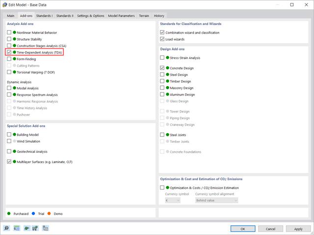
This article shows how the “Time-Dependent Analysis” add-on is integrated in RFEM 6 and RSTAB 9. It describes how to define input data such as the time-dependent characteristics of the material, how to determine the type of analysis and how to specify loading times.

In this paper, a novel approach was developed to generate CFD models at the community-level by integrating building information modeling (BIM) and geographical information systems (GIS) to automate the generation of a high-resolution 3-D community model to be employed as an input for a digital wind tunnel using RWIND.
This article summarizes the advantages of working with parameterized models in RFEM 6 and RSTAB 9.

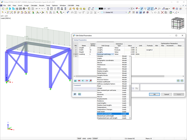
RFEM and RSTAB programs provide parameterized input as an advantageous product feature to create or adjust models by means of variables. This article will show you how to define global parameters and use them in formulas to determine numerical values.
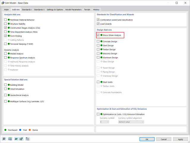
This article shows how to manage the input data for member and surface design configurations within the Stress-Strain Analysis add-on.

The advantage of the RFEM 6 Steel Joints add-on is that you can analyze steel connections using an FE model for which the modeling runs fully automatically in the background. The input of the steel joint components that control the modeling can be done by defining the components manually, or by using the available templates in the library. The latter method is included in a previous Knowledge Base article titled “Defining Steel Joint Components Using the Library". The definition of parameters for the design of steel joints is the topic of the Knowledge Base article “Designing Steel Joints in RFEM 6".

You can use the Steel Joints add-on in RFEM 6 to create and analyze steel connections using an FE model. You can control the modeling of the connections via a simple and familiar input of components. Steel joint components can be defined manually, or by using the available templates in the library. The former method is included in a previous Knowledge Base article titled “A Novel Approach to Designing Steel Joints in RFEM 6". This article will focus on the latter method; that is, it will show you how to define steel joint components using the available templates in the program’s library.

Structures in RFEM 6 can be saved as blocks and reused in other RFEM files. The advantage of dynamic blocks with respect to non-dynamic blocks is that they allow interactive modifications of the structural parameters as a result of modified input variables. One example is the possibility to add structural elements by changing only the number of bays as an input variable. This article will demonstrate the aforementioned possibility for dynamic blocks that are created by scripting.

The new generation of RFEM software is an intuitive, powerful, and easy-to-handle 3D FEA program that meets all the latest demands in modeling, calculation, and structural design. The modern design concept, as well as the introduction of new features, make the program even more innovative and user-friendly. The main differences between RFEM 6 and its previous version, RFEM 5, are discussed in the following text.

Rolled sections, the most common cross‑section type in RFEM and RSTAB, can also have user‑defined parameters. To do this, select the cross‑section to be modified in the cross‑section library and click the [Parametric Input...] button.

This article compares the design to the one in the referenced article: Design of Concrete Columns Subjected to Axial Compression with RF-CONCRETE Members. It is, therefore, about taking exactly the same theoretical application carried out in RF-CONCRETE Members and reproducing it in RF-CONCRETE Columns. Thus, the objective is to compare the different input parameters and the results obtained by the two add-on modules for the design of column-like concrete members.
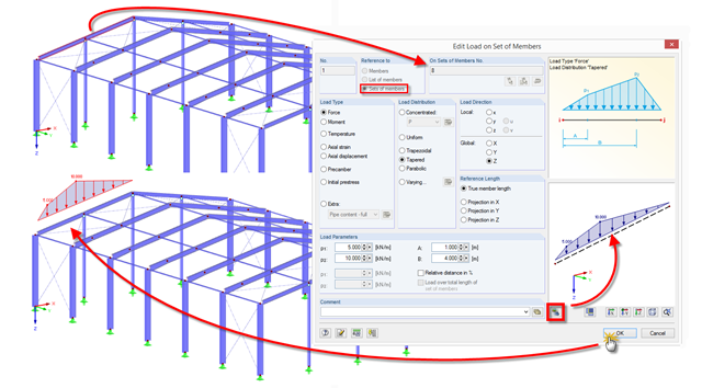
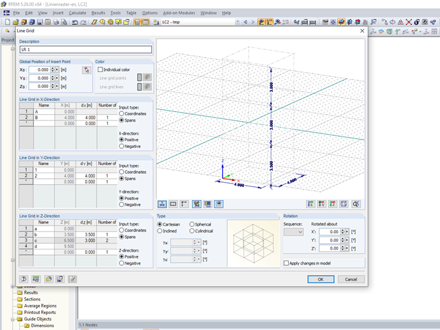
RFEM and RSTAB provide a helpful preview to check the input of member and line loads in the dialog box.
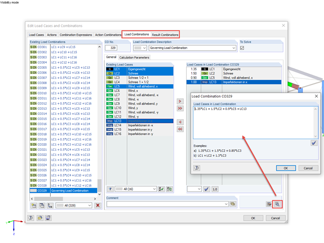
RFEM and RSTAB offer the possibility to edit or check the combinations directly by entering text.
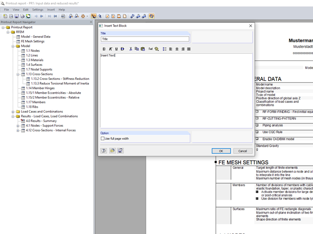
You can insert your own notes in the printout report. To do this, go to the printout report menu and click "Insert" → "Text Block."

RFEM and RSTAB save the input data, the FE mesh, the results, the printout reports, and the 3D gITF model preview, including all visual objects, in one file.

You can make various settings in order to achieve a clearly‑arranged display of the result values. For example, some users may not want the white background in text bubbles. You can adjust the background in "Display Properties" using the Transparent and Background color option.

In the RF-GLASS add-on module, 3D rendering is implemented to facilitate the definition of the support conditions. This interactive graphical visualization facilitates the input and control of line and nodal supports. However, the schematic display can also be selected, if necessary.

In the default setting, the cross-section class for each member and load case is determined automatically in the design modules. In the input window of the cross sections, however, the user can also specify the cross-section class manually; for example, if local buckling is excluded by the design.
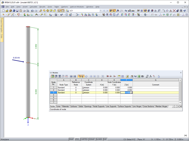
In the Formula Editor environment, you can specify any parameters (lengths, force values, and so on) to control load and geometry data in the modeling.

In RF‑/STEEL EC3, you can assign the same input data to several members or sets of members at the same time. The simultaneous assignment of the input data is possible for intermediate supports, effective lengths, nodal supports, member end hinges, and shear panel and rotational restraint.
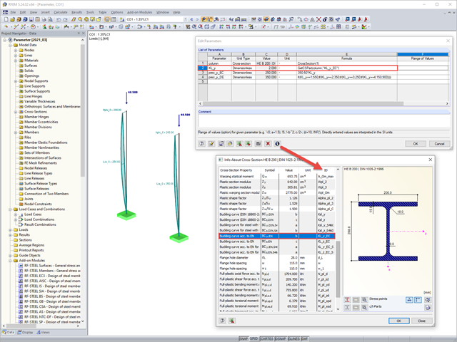
Parametric input allows you to enter the model data and load data in a specific way so they are dependent on certain variables (parameters). You can enter the parameters directly or calculate them from other parameters and constants, and furthermore, it is possible to access the cross-section values. This can be useful, for example, when calculating precambers, depending on the standard.
You can use the selection functions to facilitate the input in the tables.
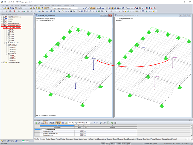
In RFEM, the load distribution is available for the result evaluation.

In EN 1993-1-1, the General Method was introduced as a design format for stability analyses that can be applied to planar systems with arbitrary boundary conditions and variable structural height. The design checks can be performed for loading in the main load-bearing plane and simultaneous compression. The stability cases of lateral-torsional buckling and flexural buckling are analyzed from the main supporting plane; that is, about the weak component axis. Therefore, the issue often arises as to how to design, in this context, flexural buckling in the main load-bearing plane.
Model and load objects can be defined graphically or in tables, or they can be created using parameters (see the manual). With this parameterized input, you can also access the cells of certain tables of the program. In this way, it is possible to link a load parameter with a model data parameter, for example. The reference is created by the $ sign.
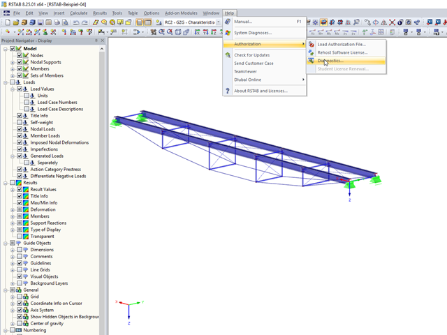
In RFEM 5 and RSTAB 8, you can view detailed information on the currently used license and installed dongle driver. In case of any problems with the license, you can send the created text file to the Dlubal Software hotline, which allows us to provide you with a fast and efficient analysis. To create the file, select "Help" → "Authorization" → "Diagnostics".
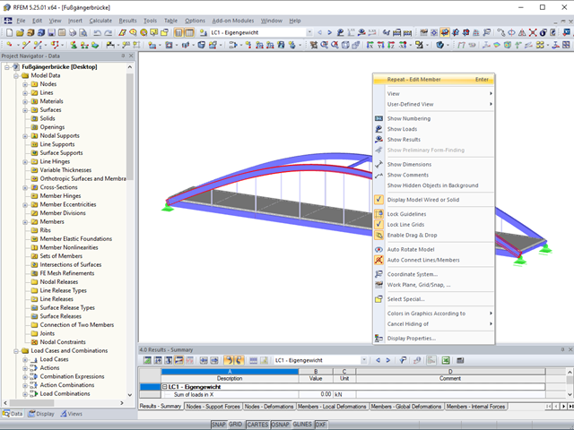
The last function used for the graphical input can easily be repeated in RFEM and RSTAB.