Question
Does the fatigue design in CRANEWAY also consider welded stiffeners?
Answer:
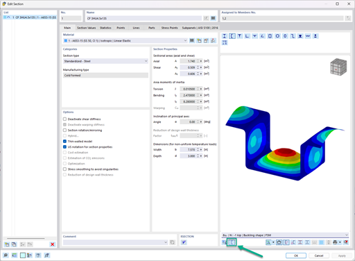
If the stiffeners are welded into the crane runway, it is necessary to consider the corresponding detail category for the fatigue design in compliance with EN 1993‑1‑9, Table 8.4, Detail 7. This is implemented in CRANEWAY by creating additional stress points at the connection point of the stiffeners to the cross-section. They can be adjusted manually in the settings for the detail categories, depending on the stiffener geometry.
During the fatigue design of the craneway girder, the design of the axial stress range is additionally performed in the newly created stress points for the x‑locations where the stiffener is.
The stiffeners and their welds are not designed separately.
Do you have any questions?
The three types of moment frames (Ordinary, Intermediate, Special) are available in the Steel Design add-on of RFEM 6. The seismic design result according to AISC 341-22 is categorized into two sections: member requirements and connection requirements.
The Steel Design add-on in RFEM 6 now offers the ability to perform seismic design according to AISC 341-16 and AISC 341-22. Five types of seismic force-resisting systems (SFRS) are currently available.
The three types of moment frames (Ordinary, Intermediate, Special) are available in the Steel Design add-on of RFEM 6. The seismic design result according to AISC 341-16 is categorized into two sections: member requirements and connection requirements.
Moment frame design according to AISC 341-16 is now possible in the Steel Design add-on of RFEM 6. The seismic design result is categorized into two sections: member requirements and connection requirements. This article covers the required strength of the connection. An example comparison of the results between RFEM and the AISC Seismic Design Manual [2] is presented.
In the ultimate configuration of the steel joint design, you have the option to modify the limit plastic strain for welds.
The "Base Plate" component allows you to design base plate connections with cast-in anchors. In this case, plates, welds, anchorages, and steel-concrete interaction are analyzed.
In the "Edit Section" dialog box, you can display the buckling shapes of the Finite Strip Method (FSM) as a 3D graphic.
- Design of five types of seismic force-resisting systems (SFRS) includes Special Moment Frame (SMF), Intermediate Moment Frame (IMF), Ordinary Moment Frame (OMF), Ordinary Concentrically Braced Frame (OCBF), and Special Concentrically Braced Frame (SCBF)
- Ductility check of the width-to thickness ratios for webs and flanges
- Calculation of the required strength and stiffness for stability bracing of beams
- Calculation of the maximum spacing for stability bracing of beams
- Calculation of the required strength at hinge locations for stability bracing of beams
- Calculation of the column required strength with the option to neglect all bending moments, shear, and torsion for overstrength limit state
- Design check of column and brace slenderness ratios
Recommended Products for You