Японский архитектурный институт (AIJ) представил ряд хорошо известных эталонных сценариев моделирования ветра.
В основе данной статьи лежит «Случай E - комплекс зданий в реальной городской зоне с плотной концентрацией малоэтажных зданий в городе Ниигата».
Далее описанный сценарий моделируется в программе RWIND2, а результаты сравниваются с результатами моделирования и эксперимента с помощью AIJ.
Das Architectural Institute of Japan (AIJ) ставит Рейхе заранее на Benchmark-Szenarien für Windsimulation vorgestellt.
Der Nachfolgende Beitrag dreht sich dabei um den «Случай А - высотное здание формы 2: 1: 1».
Im Folgenden wird das beschriebene Szenario в RWIND2 nachgebildet und die Ergebnisse mit den simulierten und der Experimentellen Resultate des AIJ verglichen.
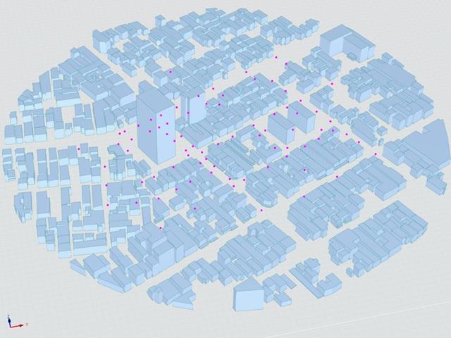
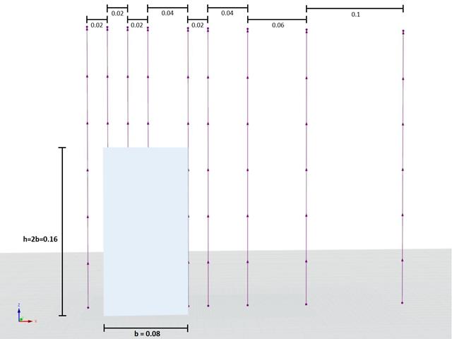
Японский архитектурный институт (AIJ) представил ряд хорошо известных эталонных сценариев моделирования ветра.
Следующая статья посвящена «случаю D - высотное здание среди городских кварталов».
Далее описанный сценарий моделируется в программе RWIND2, а результаты сравниваются с результатами моделирования и эксперимента с помощью AIJ.
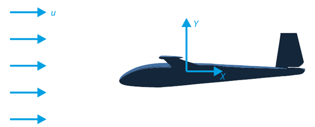
Целью данного контрольного примера является расчёт обтекания планера. Задача состоит в том, чтобы определить коэффициент лобового сопротивления и коэффициент подъёмной силы по отношению к углу атаки. Эти коэффициенты также можно изобразить на графике поляры сопротивления. Предельный угол ламинарного обтекания профиля крыла можно также можно определить по полю скоростей. Доступная 3D-модель CAD (файл STL) используется в RWIND 2.
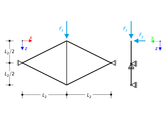
Плоская ферма, состоящая из четырех наклонных стержней и одного вертикального стержня, загружена в верхнем узле вертикальной и внеплоской силой. Assuming the large deformation analysis and neglecting the self-weight, determine the normal forces of the members and the out-of-plane displacement of the upper node.
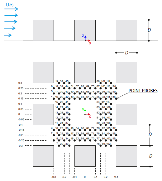
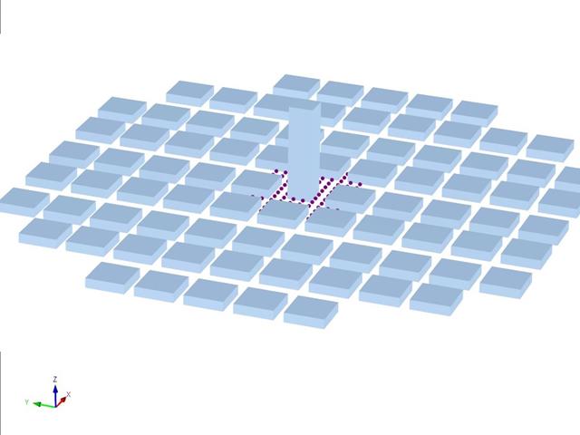
Контрольный пример описывает ветровые нагрузки в нескольких направлениях ветра на модели группы зданий. The model consists of eight cubes. The velocity fields obtained by the RWIND simulation are compared with the measured values from the experiment. The experimental data are measured using a thermistor anemometer in the wind tunnel.
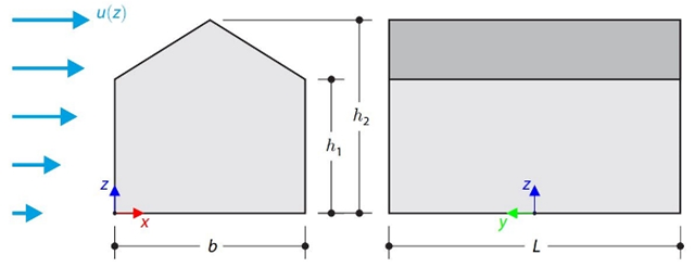
В данном контрольном примере сравниваются расчеты ветровой нагрузки на здание с двускатной кровлей по норме ASCE 7-16 и с помощью CFD моделирования в программе RWIND Simulation. The building is defined according to the sketch and the inflow velocity profile taken from the ASCE 7-16 standard.
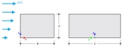
В данном контрольном примере сравниваются расчеты ветровой нагрузки на здание с плоской кровлей по норме ASCE 7-16 и с помощью CFD моделирования в программе RWIND Simulation. The building is defined according to the sketch and the inflow velocity profile taken from the ASCE 7-16 standard.
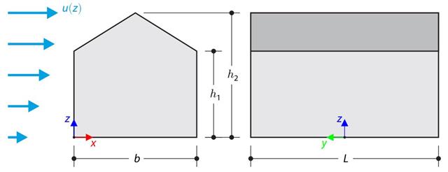
В контрольном примере сравнивается расчет ветровой нагрузки на здание с двускатной крышей по норме EN 1991-1-4 и с помощью CFD моделирования в программе RWIND Simulation. The building is defined according to the sketch, and the inflow velocity profile is taken according to the standard EN 1991-1-4.
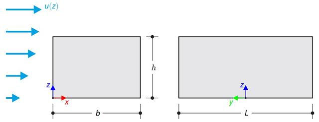
В контрольном примере сравнивается расчет ветровой нагрузки на здание с плоской кровлей по норме EN 1991-1-4 и с помощью моделирования CFD в программе RWIND Simulation. The building is defined according to the sketch, and the inflow velocity profile is taken according to the standard EN 1991-1-4.
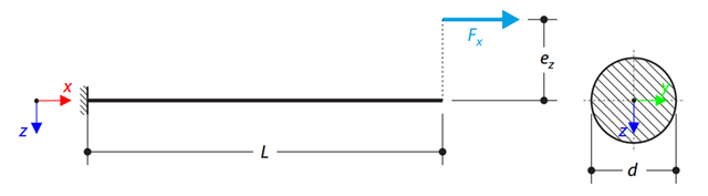
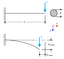
Консоль из круглого стержня нагружена внецентренной нормальной силой. Determine the maximum vertical deflection of the console using the geometrically linear and second-order analysis.
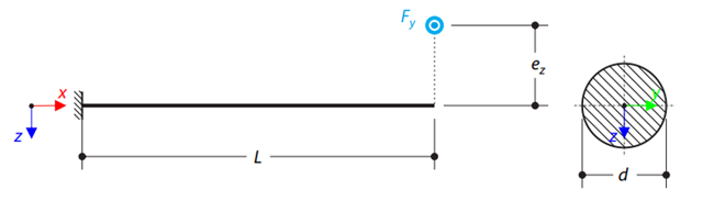
На консоль из круглого стержня действует внецентренная поперечная сила. Determine the maximum deflection and maximum twist of the console using the geometrically linear analysis.
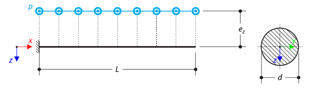
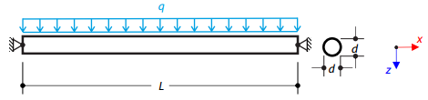
На консоль из круглого стержня действует внецентренная равномерная нагрузка. Determine the maximum deflection and maximum twist of the console using the geometrically linear analysis.
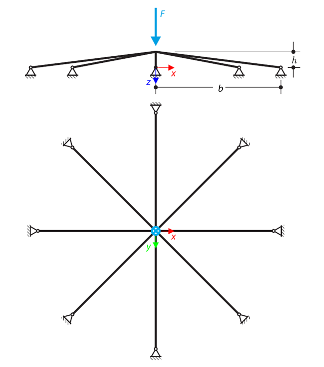
Симметричная конструкция мелкого заложения состоит из восьми одинаковых ферм, встроенных в шарнирные опоры. The structure is loaded by a concentrated force and alternatively by imposed nodal deformation over the critical limit point when the snap-through occurs. Imposed nodal deformation is used in RFEM 5 and RSTAB 8 to obtain the full equilibrium path of the snap-through. The self-weight is neglected in this example. Determine the relationship between the actual loading force and the deflection, considering large deformation analysis. Evaluate the load factor at the given deflections.
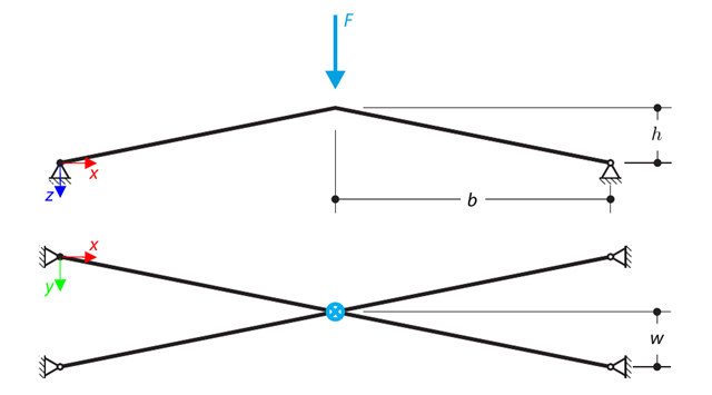
Конструкция состоит из четырех ферм, встроенных в шарнирные опоры. The structure is loaded by a concentrated force and alternatively by imposed nodal deformation over the critical limit point, when snap-through occurs. Imposed nodal deformation is used in RFEM 5 and RSTAB 8 to obtain the full equilibrium path of the snap-through. The self-weight is neglected in this example. Determine the relationship between the actual loading force and the deflection, considering large deformation analysis. Evaluate the load factor at given deflections.
Консоль загружена сосредоточенной силой на свободном конце. Determine the maximum deflection of the console using large deformation analysis.
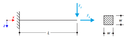
Консоль загружена поперечной и осевой силой на правом конце и полностью защемлена на левом конце. The problem is described by the following set of parameters. The problem is solved by using the geometrically linear analysis, second-order analysis, and large deformation analysis.
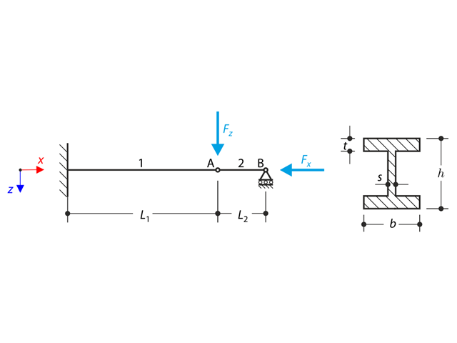
Конструкция из двутаврового профиля полностью закреплена на левом конце и встроена в подвижную опору на правом конце. The structure consists of two segments. The self-weight is neglected in this example. Determine the maximum deflection of the structure, the bending moment on the fixed end, the rotation of segment 2, and the reaction force at point B by means of the geometrically linear analysis and the second-order analysis. The verification example is based on the example introduced by Gensichen and Lumpe.
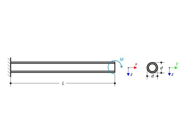
К тому же, на свободном конце консоли действует момент, Using the geometrically linear analysis and large deformation analysis, and neglecting the beam's self-weight, determine the maximum deflections at the free end. The verification example is based on the example introduced by Gensichen and Lumpe.
Расчет изменений во времени для консольной балки (система SDOF), возбужденной периодической функцией. Vertical deformations and accelerations calculated with direct integration and modal analysis in RF‑/DYNAM Pro - Forced Vibrations are compared with the analytical solution.
Стальной канат или мембрана со штифтами на обоих концах нагружены распределенной нагрузкой. Neglecting its self-weight, determine the maximum deflection of the structure using the large deformation analysis.
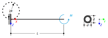
Определите изгибающий момент, действующий на свободный конец консоли, который изгибает стержень до круглой формы. Neglecting the beam's self-weight, assuming the large deformation analysis, and loading the cantilever with the moment, determine its maximum deflections.
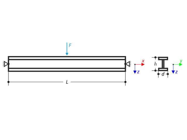
Балка, шарнирно опертая на обоих концах, загружена сосредоточенной силой в середине. Neglecting its self-weight and shear stiffness, determine the beam's maximum deflection, normal force, and moment at the mid-span, assuming the second- and third-order analysis.
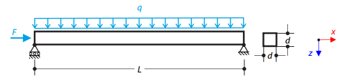
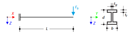
Стальная балка квадратного сечения нагружена нормальной силой и распределенной нагрузкой. The image shows the calculation of the maximum bending deflection and critical load factor according to the second-order analysis.
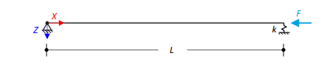
Стальная балка квадратного сечения с осевой нагрузкой имеет шарнирное закрепление на одном конце и подпружинивание - на другом. Two cases with different spring stiffnesses are considered. The verification example solves the calculation of the load factors of the beam in the image using the linear stability analysis.