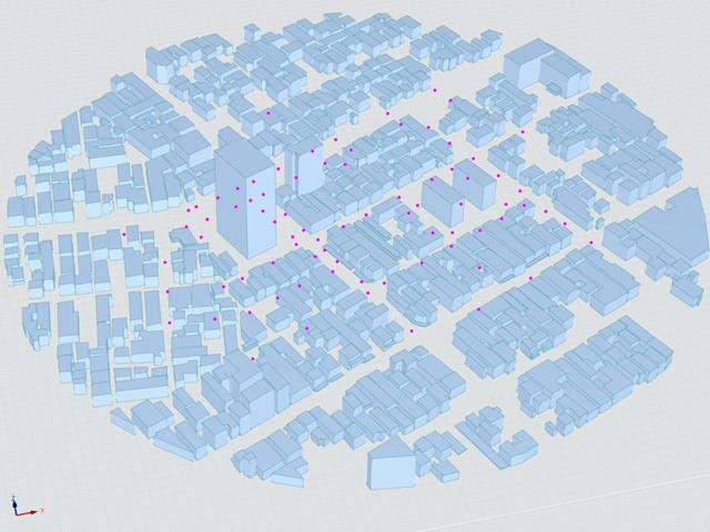
O Instituto de Arquitectura do Japão (AIJ) apresentou uma série de cenários de referência bem conhecidos para a simulação de vento.
O seguinte artigo é sobre o "Caso E - um complexo de edifícios numa área urbana real com uma densidade alta de edifícios na cidade de Niigata".
A seguir, o cenário descrito é simulado no RWIND2 e os resultados são comparados com resultados simulados e experimentais da AIJ.
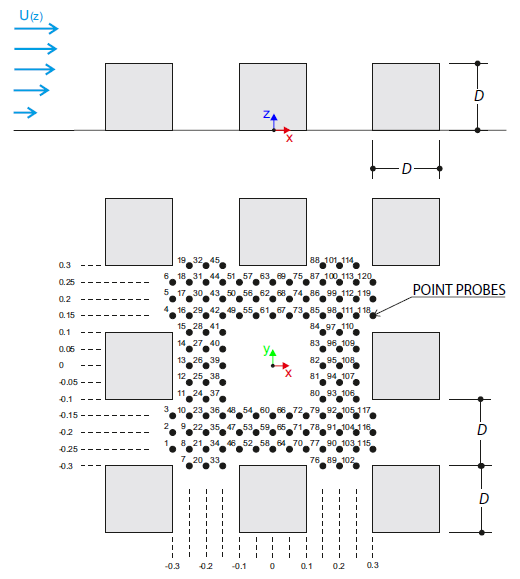
O exemplo de verificação descreve cargas de vento em várias direções do vento num modelo de um grupo de edifícios. The model consists of eight cubes. The velocity fields obtained by the RWIND simulation are compared with the measured values from the experiment. The experimental data are measured using a thermistor anemometer in the wind tunnel.
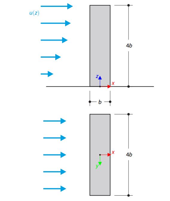
O exemplo de verificação descreve o fluxo estacionário em torno de um edifício isolado (modelo à escala) utilizando o exemplo do Instituto de Arquitetura do Japão (AIJ). The chosen results (velocity magnitude) are compared with the measured values.
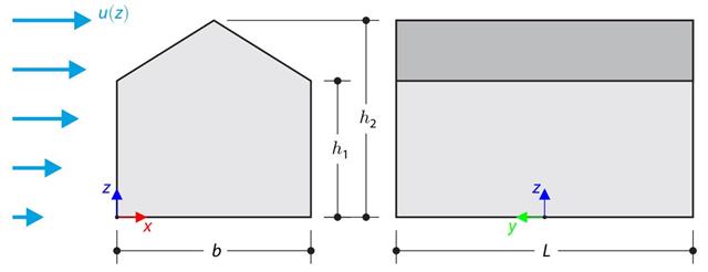
No exemplo de verificação, o cálculo de cargas de vento num edifício com cobertura de duas águas utilizando a norma EN 1991-1-4 é comparado com uma simulação CFD no RWIND Simulation. The building is defined according to the sketch, and the inflow velocity profile is taken according to the standard EN 1991-1-4.
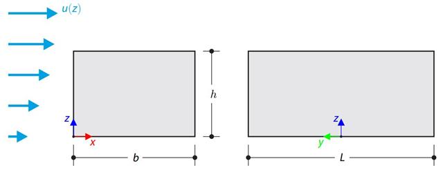
No exemplo de verificação, o cálculo da carga de vento num edifício com cobertura plana utilizando a norma EN 1991-1-4 é comparado com uma simulação CFD no RWIND Simulation. The building is defined according to the sketch, and the inflow velocity profile is taken according to the standard EN 1991-1-4.
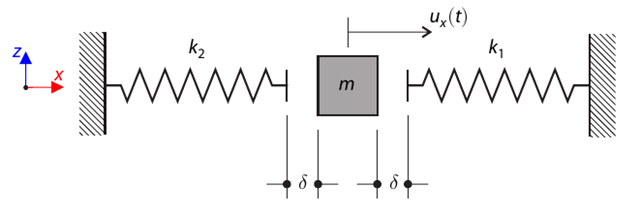
Um sistema de massa singular com folga e duas molas é desviado primeiro. Determine the natural oscillations of the system - deflection, velocity, and acceleration time course.
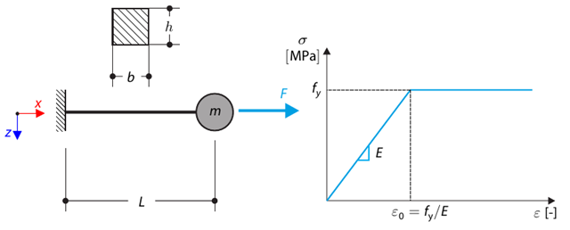
Este exemplo de verificação é baseado no exemplo de verificação 0122. A single-mass system without damping is subjected to an axial loading force. An ideal elastic-plastic material with characteristics is assumed. Determine the time course of the end-point deflection, velocity, and acceleration.
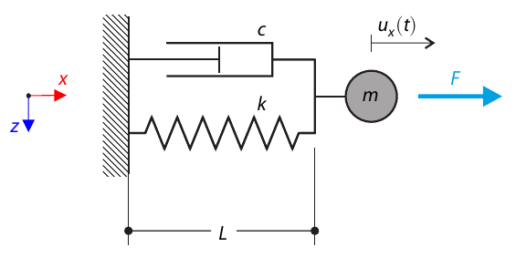
Um sistema de massa singular com amortecimento está sujeito a uma força de carga constante. Determine the deflection and velocity of the dashpot endpoint in the given test time.
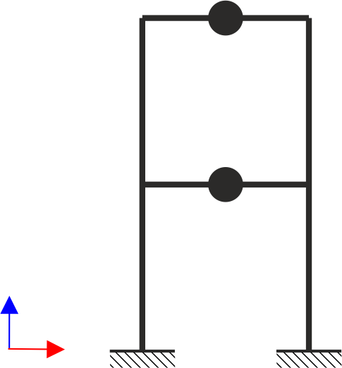
A estrutura de pórticos de dois pisos está sujeita a cargas sísmicas. The modulus of elasticity and cross‑section of the frame beams are much larger than those of the columns, so the beams can be considered rigid. The elastic response spectrum is given by the standard SIA 261/1:2003. Neglecting self-weight and assuming the lumped masses are at the floor levels, determine the natural frequencies of the structure. For each frequency obtained, specify the standardized displacements of the floors as well as equivalent forces generated using the elastic response spectrum according to the standard SIA 261/1.2003.
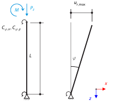
Imaginemos um tubo de andaime resistente à flexão fixado por um apoio nodal para andaimes na parte inferior e carregado por um momento e por uma força. Calculate the maximum radial deflection by exceeding the capacity of the scaffolding support.
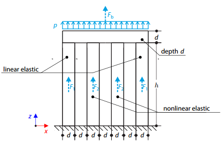
Quatro pilares estão fixados na parte inferior e ligados por um bloco rígido na parte superior. The block is loaded by pressure and modeled by an elastic material with a high modulus of elasticity. The outer columns are modeled by linear elastic material and the inner columns by a stress-strain diagram with decaying dependence. Assuming only the small deformation theory and neglecting the structure's self-weight, determine its maximum deflection.
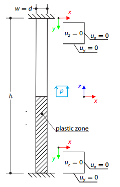
Nas duas extremidades, está fixado um bloco tridimensional de material elástico-plástico. The block's middle plane is subjected to a pressure load. The surface plasticity is described according to the Tsai-Wu plasticity theory.
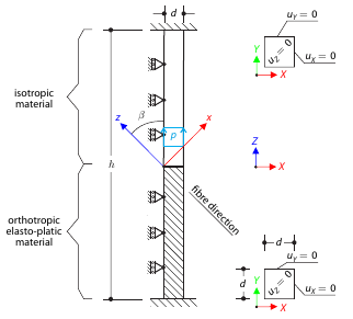
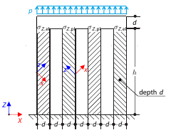
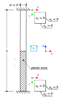
Determine the maximum deflection of a three-dimensional block fixed at both ends. The block is divided in the middle: the upper half is made of an elastic material and the lower part is made of timber - an elasto-plastic othotropic material with the yield surface described according to the Tsai-Wu plasticity theory. O plano central do bloco está sob pressão vertical.
Determine a flecha máxima de quatro pilares fixados na parte inferior, os quais estão ligados por um bloco rígido na parte superior. The block is loaded by pressure and modeled by an elastic material with a high modulus of elasticity. The outer columns are modeled as orthotropic elastic material, and the inner columns as orthotropic elastic-plastic material with the same elastic parameters as the outer columns and plasticity properties defined according to the Tsai-Wu plasticity theory.
Nas duas extremidades, está fixado um bloco tridimensional de material elástico-plástico com endurecimento. The block's middle plane is subjected to a pressure load. The surface plasticity is described according to the Tsai‑Wu plasticity theory.