O Instituto de Arquitectura do Japão (AIJ) já foi considerado um Benchmark-Szenarien für Windsimulation vorgestellt.
Der Nachfolgende Beitrag dreht sich dabei um den "Caso A - torre com a forma de 2:1:1".
Im Folgenden wird das beschriebene Szenario in RWIND2 nachgebildet und die Ergebnisse mit den simulierten und der experimentellen Resultate des AIJ verglichen.
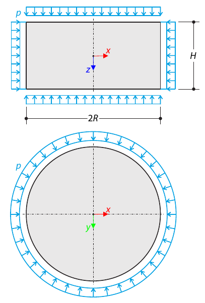
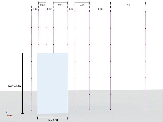
Um cilindro feito de solo elasto-plástico é sujeito a condições de teste triaxial. Negligenciando o peso próprio, o objetivo é determinar a tensão vertical limite para a rotura por corte. É considerada uma tensão hidrostática inicial de 100 kPa.
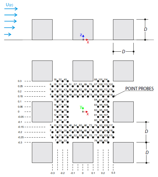
O exemplo de verificação descreve cargas de vento em várias direções do vento num modelo de um grupo de edifícios. The model consists of eight cubes. The velocity fields obtained by the RWIND simulation are compared with the measured values from the experiment. The experimental data are measured using a thermistor anemometer in the wind tunnel.
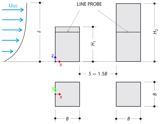
O exemplo de verificação descreve as cargas de pressão nas paredes do edifício em disposição tandem ao nível do solo. The buildings are simplified to rectangular objects and scaled down while maintaining the elevation ratios. The pressure distribution on the walls of the model of a medium-high building was conducted by an experiment. The chosen results (pressure coefficient Cp) are compared with the measured values.
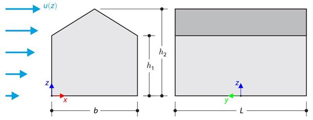
This verification example compares wind load calculations on a duopitch roof building using the ASCE 7-16 standard and using CFD simulation in RWIND Simulation. O edifício é definido conforme o esboço e o perfil da velocidade do fluxo contido na norma ASCE 7-16.
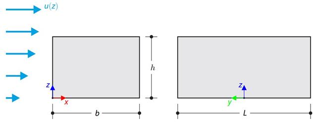
This verification example compares wind load calculations on a flat roof building using the ASCE 7-16 standard and using CFD simulation in RWIND Simulation. O edifício é definido conforme o esboço e o perfil da velocidade do fluxo contido na norma ASCE 7-16.
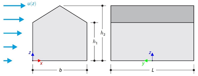
No exemplo de verificação, o cálculo de cargas de vento num edifício com cobertura de duas águas utilizando a norma EN 1991-1-4 é comparado com uma simulação CFD no RWIND Simulation. The building is defined according to the sketch, and the inflow velocity profile is taken according to the standard EN 1991-1-4.
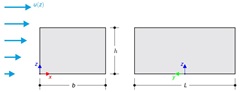
No exemplo de verificação, o cálculo da carga de vento num edifício com cobertura plana utilizando a norma EN 1991-1-4 é comparado com uma simulação CFD no RWIND Simulation. The building is defined according to the sketch, and the inflow velocity profile is taken according to the standard EN 1991-1-4.
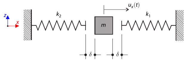
Um sistema de massa singular com folga e duas molas é desviado primeiro. Determine the natural oscillations of the system - deflection, velocity, and acceleration time course.
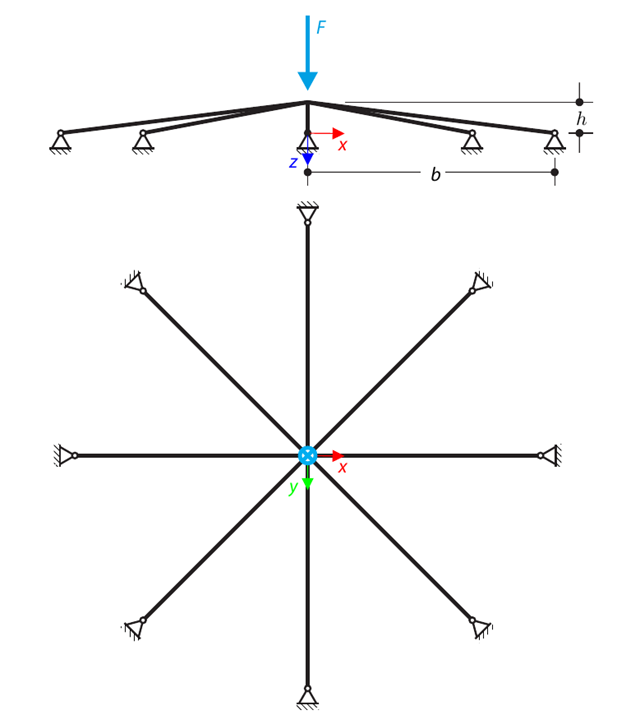
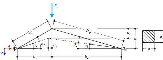
Uma estrutura plana simétrica é constituída por oito treliças idênticas encastradas em apoios articulados. The structure is loaded by a concentrated force and alternatively by imposed nodal deformation over the critical limit point when the snap-through occurs. Imposed nodal deformation is used in RFEM 5 and RSTAB 8 to obtain the full equilibrium path of the snap-through. The self-weight is neglected in this example. Determine the relationship between the actual loading force and the deflection, considering large deformation analysis. Evaluate the load factor at the given deflections.
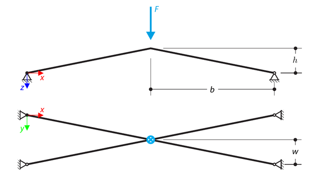
Uma estrutura é constituída por quatro treliças encastradas em apoios articulados. The structure is loaded by a concentrated force and alternatively by imposed nodal deformation over the critical limit point, when snap-through occurs. Imposed nodal deformation is used in RFEM 5 and RSTAB 8 to obtain the full equilibrium path of the snap-through. The self-weight is neglected in this example. Determine the relationship between the actual loading force and the deflection, considering large deformation analysis. Evaluate the load factor at given deflections.

Sobre uma fundação elástica Pasternak, encontra-se uma viga em consola com uma secção retangular que está sujeita a uma carga distribuída. The image shows the calculation of the maximum deflection and maximum bending moment.
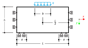
Uma alvenaria está sujeita a uma carga distribuída a meio da secção superior. The Isotropic Masonry 2D material model is compared with the Isotropic Linear Elastic model, with surface stiffness property Without Tension in the nonlinear calculation.
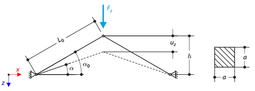
O modelo da estrutura é constituído por duas treliças de comprimento desigual que estão incorporadas nos apoios de articulação. The structure is loaded by concentrated force. The self-weight is neglected. Determine the relationship between the loading force and the deflection, considering large deformations.
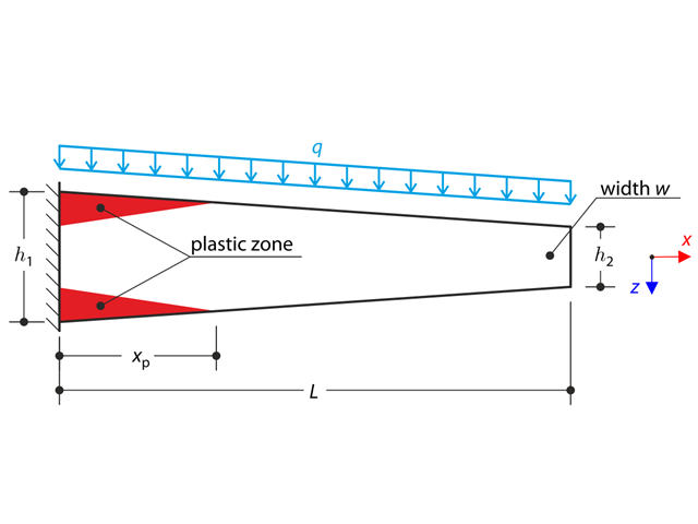
Uma viga de secção variável em consola está completamente fixada na extremidade esquerda e carregada por uma carga contínua. Plastic material is considered for the calculation.
O modelo da estrutura é constituído por duas vigas de treliça que estão incorporadas nos apoios de articulação. The structure is loaded by concentrated force. The self-weight is neglected. Determine the relationship between the loading force and the deflection, considering large deformations.
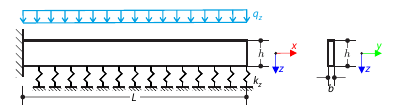
Sobre uma fundação elástica Winkler, encontra-se uma viga em consola com uma secção retangular que está sujeita a uma carga distribuída. The image shows the calculation of the maximum deflection and maximum bending moment.
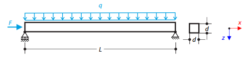
A viga de aço de secção quadrada está sujeita a uma força normal e a uma carga distribuída. The image shows the calculation of the maximum bending deflection and critical load factor according to the second-order analysis.
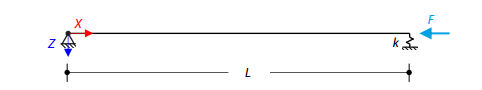
A viga de aço carregada axialmente com uma secção quadrada está apoiada sobre uma articulação numa das extremidades e sobre uma mola na outra extremidade. Two cases with different spring stiffnesses are considered. The verification example solves the calculation of the load factors of the beam in the image using the linear stability analysis.