Программа для расчёта конструкций RFEM 6 является основой нашей модульной системы программного обеспечения. Основная программа RFEM 6 используется для задания конструкций, материалов и нагрузок плоских и пространственных конструктивных систем, состоящих из плит, стен, оболочек и стержней. Программа также позволяет создавать комбинированные конструкции, а также моделировать тела и контактные элементы.
RSTAB 9 - это мощная программа для расчёта и проектирования 3D конструкций балок, каркасов или ферм, которая которая помогает инженерам-строителям соответствовать современным требованиям и отражает последние тенденции в области строительного проектирования.
Вы часто тратите слишком много времени на расчёт сечений? Программное обеспечение Dlubal и автономная программа RSECTION облегчают вашу работу, определяя характеристики и выполняя расчёт напряжений для различных сечений.
Вы всегда знаете, откуда дует ветер? Конечно, со стороны инноваций! RWIND 2 - это программа, которая использует цифровую аэродинамическую трубу для численного моделирования потоков ветра. Программа моделирует эти потоки вокруг зданий любой геометрической формы и определяет ветровые нагрузки на поверхности.
Вам нужен обзор зон снеговой, ветровой и сейсмической нагрузок? Тогда вы находитесь по адресу. Используйте инструмент Geo-Zone Tool для быстрого и лёгкого определения снеговых нагрузок, скоростей ветра и данных по сейсмике в соответствии с ASCE 7‑16 и другими нормативами различных стран.
Хотите попробовать в работе функции программ Dlubal Software? У вас есть такая возможность! Бесплатная полная версия на 90 дней позволяет вам в полной мере попробовать в работе все наши программы.
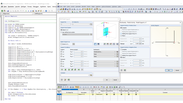
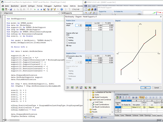
Следующий макрос VBA показывает создание узловой опоры с нелинейностью «Частичная активность». Исходный код затем находится в разделе Загрузки.
Option Explicit
' --------------------------Sub SetNSupports()' --------------------------Dim model As RFEM5.modelDim data As IModelDataDim support(0) As RFEM5.NodalSupportDim ISup As RFEM5.INodalSupportDim ISupPA как RFEM5.IPartialActivityDim nlPA как частичная активность
e: If Err.Number <> 0 Then MsgBox Err.Description, , Err.Source
End Sub
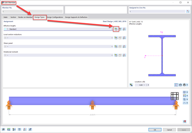
Для задания расчётных длин в RFEM 6 есть два варианта. First, edit the member and navigate to the "Design Types" Tab. Second, create a new effective lengths definition.
Third, set whether you would like to calculate the critical moment according to the Eigenvalue method or Chapter F from the AISC. Fourth, navigate to the "Nodal Supports and Effective Lengths" tab. Within this tab there are two different methods that can be used.
Метод 1: Узловые опоры и расчетные длины
Referencing Member No. 1 in the attached model, for this column you can see a how the effective lengths for the Start, End, and Intermediate nodes are defined. First, click on Select Member or Member Set and then select the member. This will activate the intermediate nodes along the member length in the table. Next, check whether the node can move in the y/z axis (weak/strong axis), rotate about its local x-axis (torsion), and about its local z-axis (LTB).
The Warping (ω) input options will adjust the effective length for LTB, similar to the rotational z-axis restraint. For Ch. F calculations, the warping can be fully restrained or released. For Eigenvalue calculations, in addition to the fully restrained or released option, there is also the ability to set partial fixity with a warping spring constant.
Top and bottom flanges can also be restrained separately by fixing the y-axis and by releasing (unchecking) the rotation about the local x-axis restraint (torsion).
Метод 2: "K" Factors and Absolute Values
Referencing Member No. 5 in the attached model, the effective length factors can be used to define the unbraced length directly and/or apply the appropriate member end conditions. To adjust the unbraced lengths directly instead of utilizing the nodes on the member (Method 1), the "K" factors can be entered manually in the table below. Or the "Absolute Values" can be entered by selecting the option "Absolute Values". Then the unbraced length itself can be entered manually instead. This method is best used when there are no intermediate nodes currently present on the member.
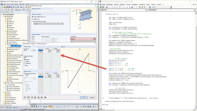
Um ein nicht lineares Element wie ein Stabendgelenk mit Diagramm oder Ausfall anlegen zu können, muss zunächst das Stabendgelenk angelegt werden. Wenn RFEM das Stabendgelenk kennt, kann dieses über die Schnittstelle IMemberEndRelease geholt werden. Diese Schnittstelle verfügt dann über die Methoden GetData() und SetData(). Beide Methoden sind in der Lage sowohl die einfachen Stabendgelenkdaten vom Typ MemberEndRelease als auch die Daten einer Nichtlinearität auszulesen bzw. zu schreiben.
Im folgenden Beispiel wird in Stabendgelenk zunächst für die x-Richtung ein Gelenk aktiviert und dann als Nichtlinearität in x-Richtung der Typ WorkingDiagramType eingestellt. Nachdem diese Daten mithilfe eines Prepare-Finish-Modification-Blocks an RFEM übergeben wurden, legt dieses intern die Nichtlinearität an. Um diese mit Daten zu füllen, werden zunächst die vorhandenen Daten über GetData() von der Schnittstelle des Stabendgelenks geholt.
Nachdem die Daten (NonlinearityDiagram) ausgefüllt wurden, werde diese wieder mit SetData() übergeben:
Sub SetNLDiagram()Dim model As RFEM5.modelSet model = GetObject(, "RFEM5.Model")On Error GoTo eDim iApp As RFEM5.ApplicationSet iApp = model.GetApplicationiApp.LockLicenseiApp.ShowDim iModelData As RFEM5.iModelDataSet iModelData = model.GetModelData' modify member end release' set nonlinearity "Diagram" for x translationDim iMemHing As RFEM5.IMemberHingeSet iMemHing = iModelData.GetMemberHinge(1, AtNo)Dim memHing As RFEM5.MemberHingememHing = iMemHing.GetData()memHing.TranslationalConstantX = 0memHing.TranslationalNonlinearityX = WorkingDiagramType' Set new dataiModelData.PrepareModificationiMemHing.SetData memHingiModelData.FinishModification' create diagramDim tbl1() As DoubleReDim tbl1(1, 1)tbl1(0, 0) = 0 ' u-xtbl1(0, 1) = 0 ' P-xtbl1(1, 0) = 0.02 ' u-x (mm)tbl1(1, 1) = 2000 ' P-x (N)Dim nldHing As RFEM5.NonlinearityDiagramnldHing.ForceType = StiffnessDiagramForceType.NoneStiffnessForcenldHing.PositiveZoneType = DiagramAfterLastStepType.TearingDiagramTypenldHing.PositiveZone = tbl1nldHing.Symmetric = TrueDim iNldiag As RFEM5.INonlinearityDiagramSet iNldiag = iMemHing.GetNonlinearity(AlongAxisX)' Set new dataiModelData.PrepareModificationiNldiag.SetData nldHingiModelData.FinishModificatione: If Err.Number <> 0 Then MsgBox Err.description, , Err.Sourcemodel.GetApplication.UnlockLicenseEnd Sub
Die Vorgehensweise ist für Knotenlager und andere Nichtlinearitäten analog.
When you upgrade an RFEM 5 add-on module such as RF-STEEL AISC, you will now have access to all national and international standards in RFEM 6 including AISC 360, CSA S16, EC3, and many more. The separate standards under each design material are no longer sold as separate modules. If you currently have multiple modules for the separate standards (e.g. RF-STEEL AISC and RF-STEEL CSA), there will only be one upgrade fee for a material family. This will be a long-term cost savings.
RFEM 5 is supported in parallel to RFEM 6 and will be maintained with further updates. These updates mainly include the correction of small program bugs as well as adjustments to changes in operating systems and graphics cards in order to maintain functionality. New features and further developments are implemented exclusively in the RFEM 6 software generation.
Support for RFEM 5 continues until further notice as long as there is a valid service contract for RFEM 5. In order to benefit from upgrade conditions, a valid service contract for RFEM 5 is also required.
Purchased RFEM 5 licenses can continue to be used in parallel with RFEM 6 even after a complete upgrade to RFEM 6.
RFEM 5 and RFEM 6 will have separate service contracts with the two levels Basic and Pro available for both generations. You can maintain your RFEM 5 service contract to continue receiving program updates and priority tech support. If you choose to discontinue the RFEM 5 service contract, you can continue using the program but will no longer have access to any program updates.
One significant difference from the RFEM 5 service contract is that when a service contract is purchased for RFEM 6, it will also be required to purchase a service contract for each add-on. The reason for this is you now have access to all national and international standards for a given material (e.g. concrete design acc. to ACI 318, CSA A23.3, EC2, etc. in one add-on). Program updates will include significant updates for the add-ons including the addition of new standards when available.
It’s highly suggested that a service contract is purchased for RFEM 6 as significant development will continue over the next several years for this new generation and will be provided through program updates to those with a valid service contract. Both the Basic and Pro levels will provide access to the latest program updates while the Basic will provide priority email technical support only and the Pro will provide priority email, phone, and screen-sharing technical support.
We are pleased that RFEM 6 licensing configuration is entirely cloud based. You only need your login credentials to access the program from any computer at any location. Therefore, we will no longer offer a standalone vs. a network license which required the license manager to be installed on either a client computer or server as this was the case with RFEM 5.
Additionally, the upgrade cost for an existing RFEM 5 network vs. standalone license will be the same for both.
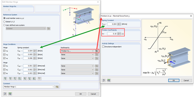
Трение - это тип нелинейности, который можно изменить только через интерфейс к шарниру стержня.
Для этого сначала необходимо создать шарнир стержня, если он еще не создан. Затем применим к шарниру стержня интерфейс IMemberHinge, а к нелинейности интерфейс IFriction. После того уже можно для изменения требуемых данных (в данном случае это запись Friction) использовать методы GetData и SetData:
Sub SetMemberHingeFriction() Dim model As RFEM5.model Set model = GetObject(, "RFEM5.Model") model.GetApplication.LockLicense On Error GoTo e Dim data As IModelData Set data = model.GetModelData Dim hinge(0 To 0) As RFEM5.MemberHinge hinge(0).No = 1 hinge(0).RotationalConstantX = 1 hinge(0).RotationalConstantY = 2 hinge(0).RotationalConstantZ = 3 hinge(0).TranslationalConstantX = 4 hinge(0).TranslationalConstantY = 5 hinge(0).TranslationalConstantZ = 6 hinge(0).Comment = "Member Hinge 1" hinge(0).TranslationalNonlinearityX = FrictionAType data.PrepareModification data.SetMemberHinges hinge data.FinishModification ' get interface for member hinge Dim imemhing As IMemberHinge Set imemhing = data.GetMemberHinge(1, AtNo) ' get interface for nonlinearity "friction" Dim iFric As IFriction Set iFric = imemhing.GetNonlinearity(AlongAxisX) ' get friction data Dim fric As Friction fric = iFric.GetData fric.Coefficient1 = 0.3 ' set friction data data.PrepareModification iFric.SetData fric data.FinishModification e: If Err.Number <> 0 Then MsgBox Err.Description, , Err.Source Set data = Nothing model.GetApplication.UnlockLicense Set model = NothingEnd Sub
В случае трения Vy + Vz, используется для настройки второго коэффициента команда Coefficient2. Постоянная пружины в диалоговом окне «Трение» затем определяется с помощью продольной пружины шарнира стержня. В данном конкретном случае это запись TranslationalConstantX , которая управляет настройками для направления x (см. Рисунок 01).
Способ создания узловой опоры с диаграммой нелинейности показан в следующем макросе VBA. Исходный код затем находится в разделе Загрузки.