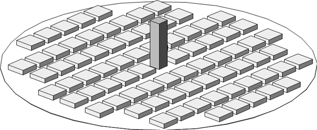
Контрольный пример описывает ветровые нагрузки в нескольких направлениях ветра на модели группы зданий. The model consists of eight cubes. The velocity fields obtained by the RWIND simulation are compared with the measured values from the experiment. The experimental data are measured using a thermistor anemometer in the wind tunnel.
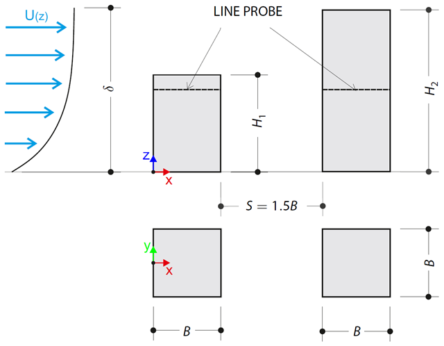
Контрольный пример описывает сжимающие нагрузки на стены зданий в тандемном расположении, расположенных на уровне земли. The buildings are simplified to rectangular objects and scaled down while maintaining the elevation ratios. The pressure distribution on the walls of the model of a medium-high building was conducted by an experiment. The chosen results (pressure coefficient Cp) are compared with the measured values.
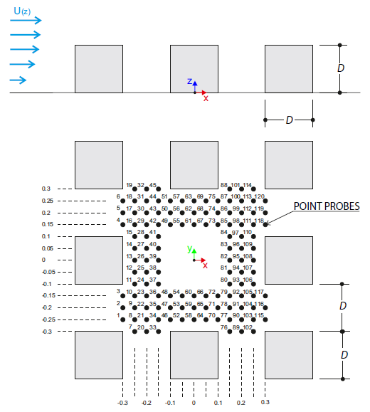
Контрольный пример описывает стационарный поток вокруг высотного здания в городской застройке (масштабная модель). The example is given by the Architectural Institute of Japan (AIJ). The chosen results (velocity magnitude) are compared with the measured values.
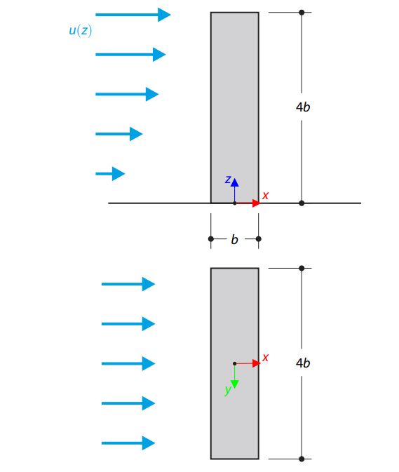
Контрольный пример описывает стационарный поток вокруг отдельностоящего здания (масштабированная модель).Пример был предоставлен Архитектурным институтом Японии (AIJ). The chosen results (velocity magnitude) are compared with the measured values.
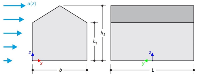
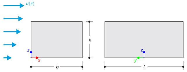
В данном контрольном примере сравниваются расчеты ветровой нагрузки на здание с двускатной кровлей по норме ASCE 7-16 и с помощью CFD моделирования в программе RWIND Simulation. The building is defined according to the sketch and the inflow velocity profile taken from the ASCE 7-16 standard.
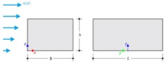
В данном контрольном примере сравниваются расчеты ветровой нагрузки на здание с плоской кровлей по норме ASCE 7-16 и с помощью CFD моделирования в программе RWIND Simulation. The building is defined according to the sketch and the inflow velocity profile taken from the ASCE 7-16 standard.
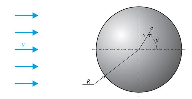
A sphere is subjected to a uniform flow of viscous fluid. The velocity of the fluid is considered at infinity. The goal is to determine the drag force. The parameters of the problem are set so that the Reynolds number is small and the radius of the sphere is also small, thus the theoretical solution can be reached - Stokes flow (G. G. Stokes 1851).
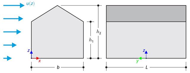
В контрольном примере сравнивается расчет ветровой нагрузки на здание с двускатной крышей по норме EN 1991-1-4 и с помощью CFD моделирования в программе RWIND Simulation. The building is defined according to the sketch, and the inflow velocity profile is taken according to the standard EN 1991-1-4.
В контрольном примере сравнивается расчет ветровой нагрузки на здание с плоской кровлей по норме EN 1991-1-4 и с помощью моделирования CFD в программе RWIND Simulation. The building is defined according to the sketch, and the inflow velocity profile is taken according to the standard EN 1991-1-4.
- 000119
- Расчет
- RFEM 5
-
- RSTAB 8
- RF-DYNAM Pro | Natural Vibrations 5
- RF-DYNAM Pro | Forced Vibrations 5
- RF-DYNAM Pro | Equivalent Loads 5
- RF-DYNAM Pro | Nonlinear Time History 5 (нелинейное изменение во времени)
- DYNAM Pro | Natural Vibrations 8 (собственные колебания)
- DYNAM Pro | Equivalent Loads (Эквивалентные нагрузки) 8
- DYNAM Pro | Nonlinear Time History 8
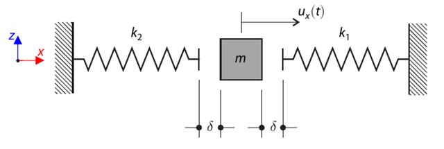
Сначала прогибается система с одной массой, с допуском и двумя пружинами. Determine the natural oscillations of the system - deflection, velocity, and acceleration time course.
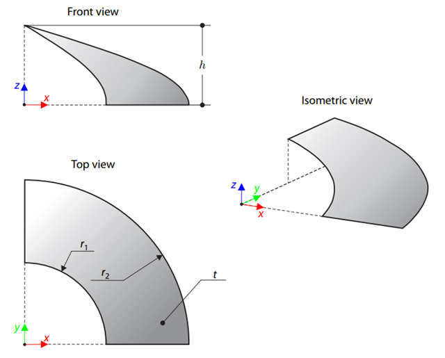
Мембрана растягивается посредством изотропного преднапряжения между двумя радиусами двух концентрических цилиндров, не лежащих в плоскости, параллельной вертикальной оси. Find the final minimum shape of the membrane - the helicoid - and determine the surface area of the resulting membrane. The add-on module RF-FORM-FINDING is used for this purpose. Elastic deformations are neglected both in RF-FORM-FINDING and in the analytical solution; self-weight is also neglected in this example.
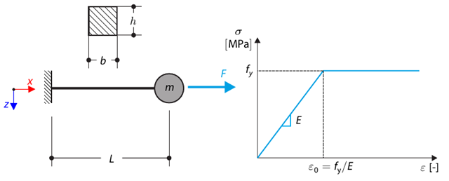
Данный контрольный пример основан на контрольном примере 0122. A single-mass system without damping is subjected to an axial loading force. An ideal elastic-plastic material with characteristics is assumed. Determine the time course of the end-point deflection, velocity, and acceleration.
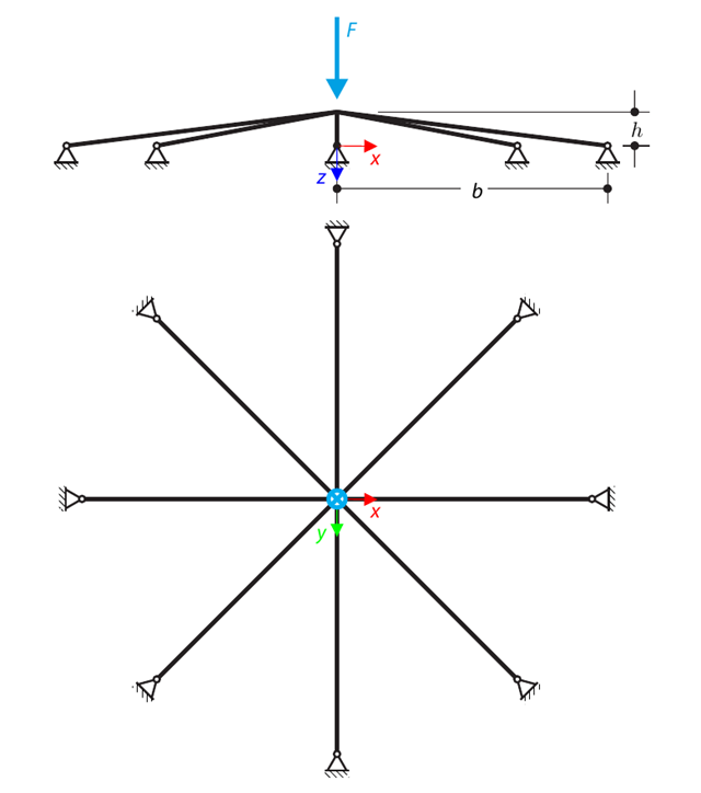
Симметричная конструкция мелкого заложения состоит из восьми одинаковых ферм, встроенных в шарнирные опоры. The structure is loaded by a concentrated force and alternatively by imposed nodal deformation over the critical limit point when the snap-through occurs. Imposed nodal deformation is used in RFEM 5 and RSTAB 8 to obtain the full equilibrium path of the snap-through. The self-weight is neglected in this example. Determine the relationship between the actual loading force and the deflection, considering large deformation analysis. Evaluate the load factor at the given deflections.
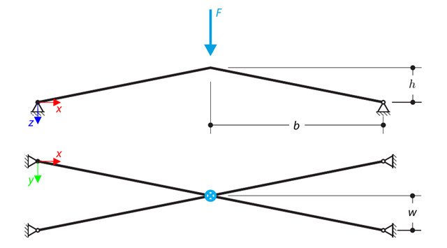
Конструкция состоит из четырех ферм, встроенных в шарнирные опоры. The structure is loaded by a concentrated force and alternatively by imposed nodal deformation over the critical limit point, when snap-through occurs. Imposed nodal deformation is used in RFEM 5 and RSTAB 8 to obtain the full equilibrium path of the snap-through. The self-weight is neglected in this example. Determine the relationship between the actual loading force and the deflection, considering large deformation analysis. Evaluate the load factor at given deflections.
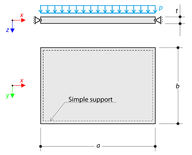
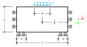
Тонкая прямоугольная ортотропная пластина оперта просто, и она загружена равномерно распределенным давлением. The directions of axes x and y coincide with the principal directions. While neglecting self-weight, determine the maximum deflection of the plate.
- 000120
- Расчет
- RFEM 5
-
- RSTAB 8
- RF-DYNAM Pro | Natural Vibrations 5
- RF-DYNAM Pro | Forced Vibrations 5
- RF-DYNAM Pro | Equivalent Loads 5
- RF-DYNAM Pro | Nonlinear Time History 5 (нелинейное изменение во времени)
- DYNAM Pro | Natural Vibrations 8 (собственные колебания)
- DYNAM Pro | Equivalent Loads (Эквивалентные нагрузки) 8
- DYNAM Pro | Nonlinear Time History 8
Система единичных масс с амортизатором находится под действием постоянной силы нагрузки. Determine the deflection and velocity of the dashpot endpoint in the given test time.
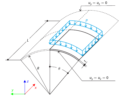
У конструкции кровли оболочки, находящейся под нагрузкой давления, прямые края являются свободными, а на изогнутых краях перемещения y и z ограничены. Neglecting self‑weight, compute the maximum (absolute) vertical deflection, and compare the results with COMSOL Multiphysics 4.3.
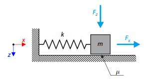
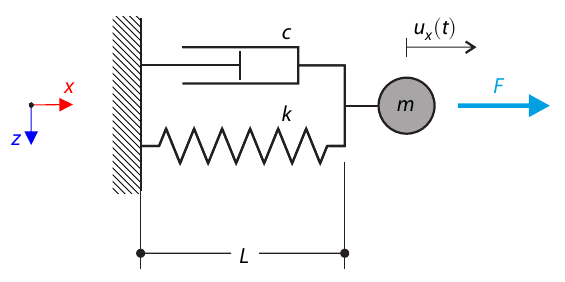
Простой осциллятор состоит из массы m (рассчитываемой только в направлении x) и линейной пружины с жесткостью k. The mass is embedded on a surface with Coulomb friction and is loaded by constant-in-time axial and transverse forces.
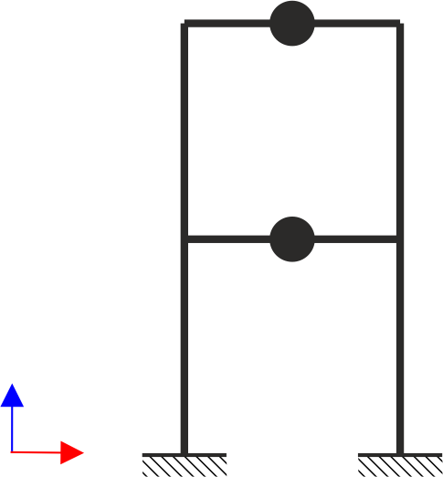
Двухэтажная однопролетная каркасная конструкция подвержена сейсмической нагрузке. The modulus of elasticity and cross‑section of the frame beams are much larger than those of the columns, so the beams can be considered rigid. The elastic response spectrum is given by the standard SIA 261/1:2003. Neglecting self-weight and assuming the lumped masses are at the floor levels, determine the natural frequencies of the structure. For each frequency obtained, specify the standardized displacements of the floors as well as equivalent forces generated using the elastic response spectrum according to the standard SIA 261/1.2003.
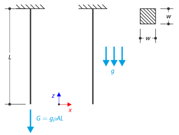
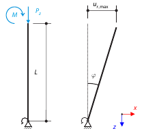
На верхнем конце затем закреплен стержень квадратного сечения. The rod is loaded by self-weight. For comparison, the example is also modeled with the concentrated force load, the value of which is equal to the gravity. The aim of this verification example is to show the difference between these types of loading, although the total loading force is equal.
Рассмотрим жесткую трубу строительных лесов, закрепленную снизу с помощью Узловой опоры лесов и нагруженную моментом и силой. Calculate the maximum deflection with consideration of initial slippage.
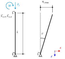
Рассмотрим жесткую трубу строительных лесов, закрепленную снизу с помощью Узловой опоры лесов и нагруженную моментом и силой. Calculate the maximum radial deflection by exceeding the capacity of the scaffolding support.
Расчет изменений во времени для консольной балки (система SDOF), возбужденной периодической функцией. Vertical deformations and accelerations calculated with direct integration and modal analysis in RF‑/DYNAM Pro - Forced Vibrations are compared with the analytical solution.
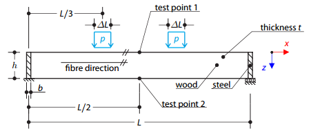
Деревянная балка, усиленная на концах двумя стальными пластинами, подвергается нагрузке давления. The wood fibers are parallel to the upper loaded side of the beam. The plastic surface is described according to the Tsai-Wu plasticity theory.
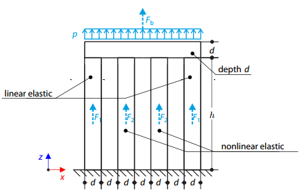
Четыре колонны закреплены снизу и соединены жестким блоком наверху. The block is loaded by pressure and modeled by an elastic material with a high modulus of elasticity. The outer columns are modeled by linear elastic material and the inner columns by a stress-strain diagram with decaying dependence. Assuming only the small deformation theory and neglecting the structure's self-weight, determine its maximum deflection.
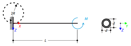
Определите изгибающий момент, действующий на свободный конец консоли, который изгибает стержень до круглой формы. Neglecting the beam's self-weight, assuming the large deformation analysis, and loading the cantilever with the moment, determine its maximum deflections.
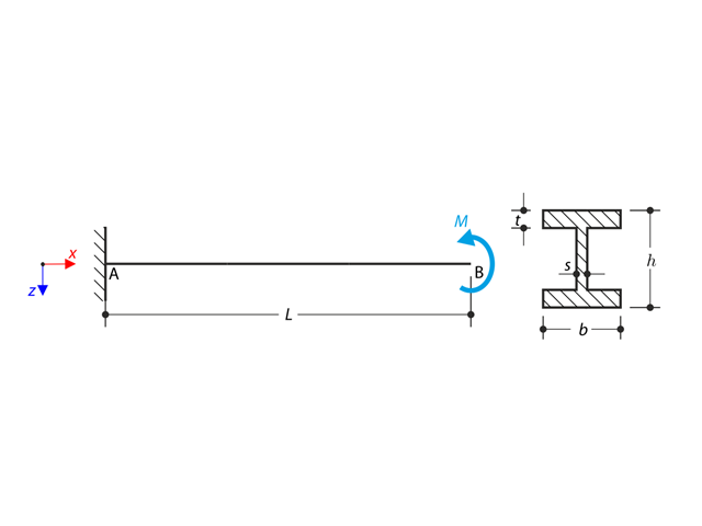
На левом конце поддерживается двутавровая консоль, которая нагружена крутящим моментом. The aim of this example is to compare the fixed support with the fork support and to investigate the behavior of some representative quantities. Comparison is also made to the solution by means of plates. Small deformations are considered, and the self-weight is neglected. Determine the rotation in the midpoint of the cantilever, and in case of the member entity with warping, determine the values of the primary torsional moment, the secondary torsional moment, and the warping moment both on the left end (point A) and the right end (point B).
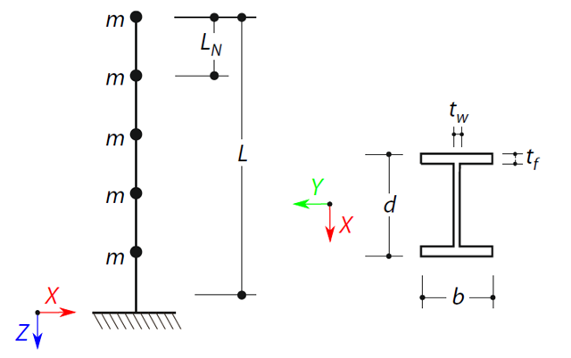
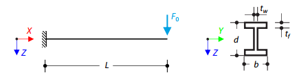
A cantilever beam with an I-beam cross-section of length L is defined. The beam has five mass points with masses m acting in the X-direction. Собственный вес не учитывается. The frequencies, mode shapes, and equivalent loads of this 5-DOF system are analytically calculated and compared with the results from RSTAB and RFEM.
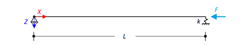
Стальная балка квадратного сечения с осевой нагрузкой имеет шарнирное закрепление на одном конце и подпружинивание - на другом. Two cases with different spring stiffnesses are considered. The verification example solves the calculation of the load factors of the beam in the image using the linear stability analysis.