


Предмет:
Расчет стержней, устойчивых к моменту, по норме AISC 341-22 в программе RFEM 6
Комментарий:
В аддоне Расчёт стальных конструкций для RFEM 6 содержатся три типа рам, воспринимающих момент (обычные, промежуточные и специальные). Результат сейсмического расчета по AISC 341-22 подразделяется на две части: требования к стержням и требования к соединениям.
Легенда:
Более подробная информация о вводе сейсмической конфигурации описана в отдельной статье.
КБ | Сейсмический расчёт по AISC 341 в программе RFEM 6
.
Требования к стержню
В программе RFEM имеются следующие виды расчетов для стержней, являющихся частью устойчивой к сейсмической нагрузке системы (SFRS). Перечисленные сечения относятся к сейсмическим нормам AISC 341-22 [1].
- Ограничения ширины к толщине [Раздел D1.1]
- Связи устойчивости балок - требуемая прочность и жесткость [сечение D1.2a.1(b) для IMF и D1.2b для SMF]
- Связи устойчивости балок - максимальный шаг [раздел D1.2a.1(c) для IMF и D1.2b для SRF]
- Связи устойчивости балок в местах шарниров - требуемая прочность [Раздел D1.2c.1(b)]
- Требуемая прочность колонны [Раздел D1.4a]
- Коэффициент гибкости колонны для соединения без связей [Сечение E3.4c.2b]
Ограничения ширины к толщине для требований к податливости
Стержни в IMF заданы как умеренно податливые стержни согласно п. E2.5a. Стержни в SMF заданы как высоко податливые стержни согласно п. E3.5a.
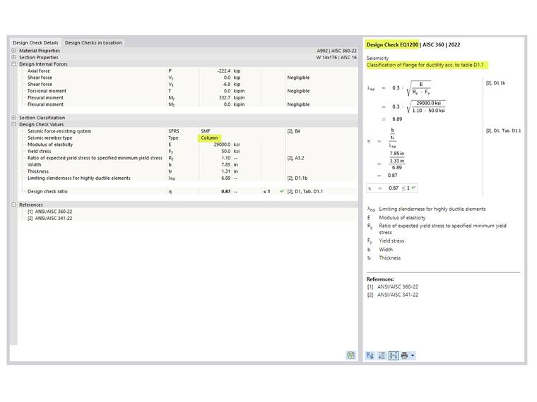
'''Полка колонны'''
Полка колонны SMF должна удовлетворять требованиям AISC Seismic Profisions, раздел D1.1 [1] для высоко податливых стержней. Данный расчет отображен в RFEM как EQ 1200 (рисунок 1).
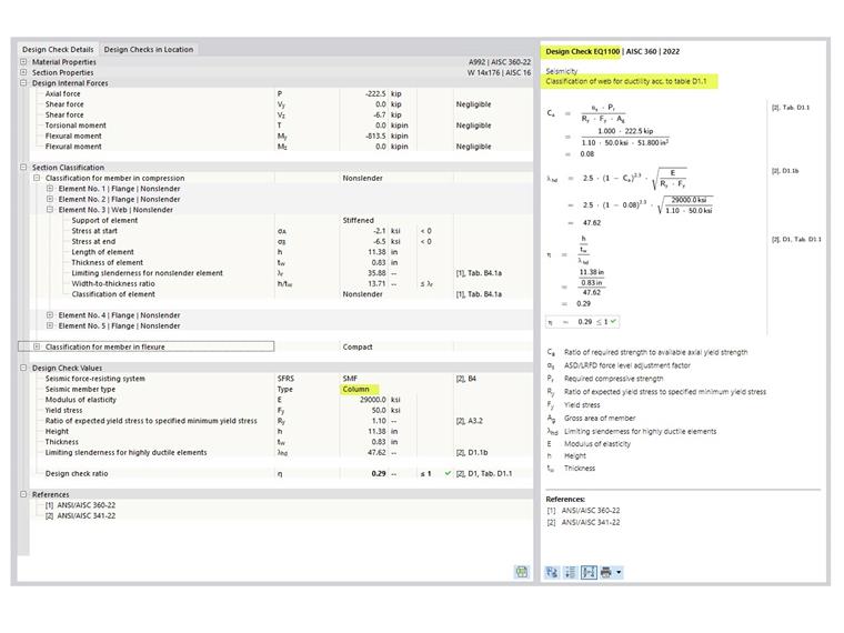
'''Стенка колонны'''
Предельное отношение ширины к толщине для стенок высоко податливых стержней определяется с помощью определяющего загружения для осевой нагрузки, как указано в разделе D1.4a [1]. Определяющее загружение основано на всех сочетаниях нагрузок, включая СН только с гравитацией, СН со стандартной сейсмической нагрузкой и СН с сейсмической нагрузкой сверхпрочности. Данный расчет показан в EQ 1100 в программе RFEM (рисунок 2).
Аналогично колоннам, проверки соотношения ширины и толщины выполняются для балок.
Связи устойчивости балок
Требуемая прочность и жесткость связей устойчивости указаны на вкладке «связи устойчивости по стержням» в разделе «сейсмические требования» (рисунок 3). Эти значения можно сравнить с рассчитанными для имеющейся прочности и жесткости при расчете элементов жесткости, которые соединяются с балкой. Подробности расчета не доступны (только ссылки).
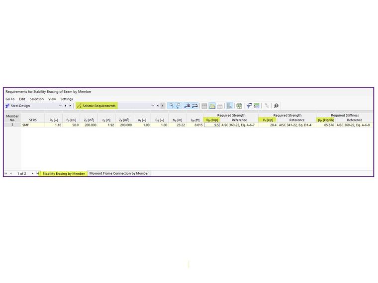
Для требуемой прочности указаны два различных значения. Первое значение, P-br, применяется для связей устойчивости, которые расположены за пределами позиции пластического шарнира. P-br определяется в уравнении A-6-7 в Приложении 6 к AISC 360 [3]:
|
Pbr |
Требуемая прочность стабилизирующей обрешётки балок |
|
Mr |
Требуемая прочность балки на изгиб. Mr = RyFyZ/αs [Уравнение AISC 341 D1-1] |
|
Cd |
Коэффициент двойной кривизны = 1,0 [AISC 341 Раздел D1.2a(b)] |
|
ho |
Расстояние между центрами поясов ho = d - tf |
Второе, большее значение, Pr, предназначено специально для связей устойчивости в месте пластического шарнира. Она определяется уравнением D1-4 в норме AISC 341 [1]:
|
Pr |
Required strength of the stability beam bracing at the plastic hinge location |
|
Ry |
Ratio of the expected yield stress to the specified minimum yield stress |
|
Fy |
Specified minimum yield stress |
|
Z |
Effective plastic section modulus of a section (or a connection) at the plastic hinge location |
|
αs |
LRFD-ASD force level adjustment factor = 1.0 for LRFD and 1.5 for ASD |
|
ho |
Distance between the flange centroid |
Требуемая жесткость β-br определена по уравнению A-6-8 в Приложении 6:
|
βbr |
Required stiffness of the stability beam bracing |
|
Mr |
Required flexural strength of the beam |
|
Cd |
Double curvature factor = 1.0 |
|
Lbr |
Maximum spacing of the stability beam bracing |
|
ho |
Distance between the flange centroid |
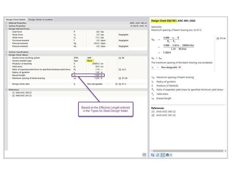
Максимальный шаг связей устойчивости должен удовлетворять требованиям AISC 341-22, раздел D1.2a.1 (c) для IMF и раздел D1.2b для SMF.
|
Lbr |
Maximum spacing of the stability beam bracing |
|
ry |
Radius of gyration about the weak axis |
|
E |
Modulus of elasticity |
|
Ry |
Ratio of the expected yield stress to the specified minimum yield stress |
|
Fy |
Specified minimum yield stress |
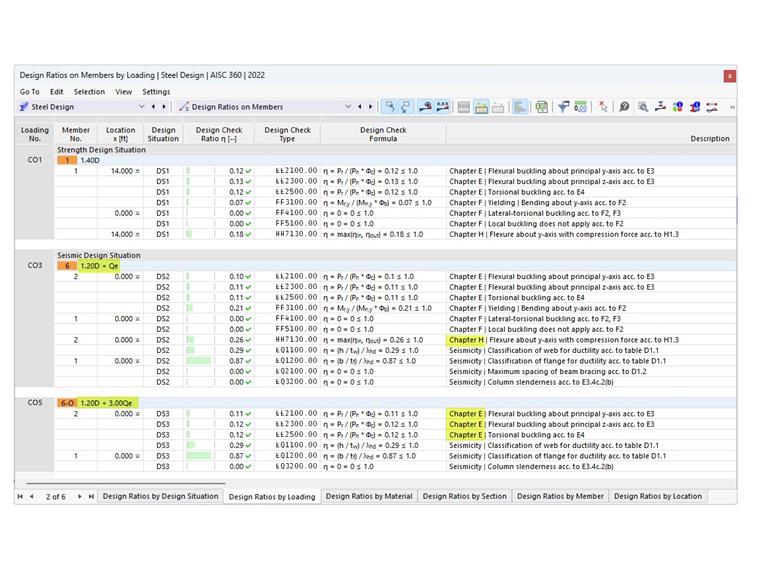
Расчет максимального шага представлен наряду с другими требованиями к стержням в разделе «расчетные соотношения стержней». Подробности расчета показаны в EQ 2100 (рисунок 4). Длина связи Lb - это заданная свободная длина для потери устойчивости плоской формы изгиба (LTB).
Требуемая прочность колонны
Все колонны, входящие в сейсмоустойчивую систему (SFRS), должны быть рассчитаны со сверхпрочными нагрузками. Во многих случаях нет необходимости сочетать увеличенную нормальную силу с сопутствующими изгибающими моментами. Опция пренебрежения всеми изгибающими моментами, сдвигом и кручением в колоннах для предельного состояния по сверхпрочности активирована по умолчанию. Данную функцию можно отключить в сейсмической конфигурации.
Для стандартных сочетаний нагрузок без увеличения прочности от действия сейсмической нагрузки комбинированное нагружение проверяется по AISC 360-22, глава H.
Для сочетаний нагрузок с сейсмической нагрузкой сверхпрочности расчет по главе F и H не производится в случае, если активирована опция пренебрежения всеми изгибающими моментами, сдвигом и кручением в колоннах для предельного состояния сверхпрочности.
В примере 4.3.2 руководства по сейсмике [2] должен быть рассмотрен контрольный случай из обоих сочетаний нагрузок, стандартного и сверхпрочного.
Изгибающие моменты, возникающие в результате нагрузки, приложенной между точками боковых опор, могут вызвать потерю устойчивости колонны. Поэтому их необходимо учитывать одновременно с осевыми нагрузками, отключив опцию пренебрежения моментами.
Коэффициент гибкости колонны для соединения без связей
Для колонн в SRF без связей поперечных стержней в соединении, потенциальная потеря устойчивости соединения из плоскости должна быть мин.