- Рамы с особым моментом (SMF)
- Рама с промежуточным моментом (IMF)
- Рамы с начальным моментом (OMF)
- Типовой соосно связанный жёсткий каркас (OCBF)
- Нетиповой соосно связанный жёсткий каркас (SCBF)
Ввод сейсмической конфигурации
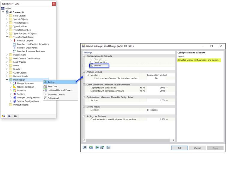
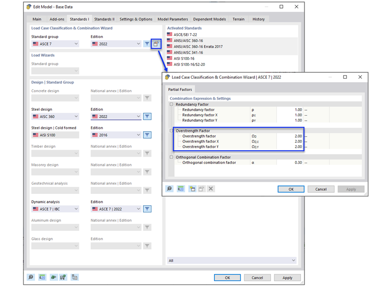
Соответствующие исходные данные для расчета задаются в сейсмической конфигурации. Сейсмическую конфигурацию можно активировать в общих настройках папки «Расчет стальных конструкций» (рисунок 1).
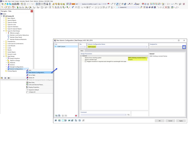
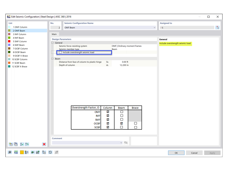
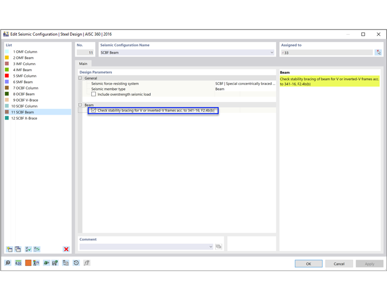
После этого вы можете задать новую сейсмическую конфигурацию путем ввода описательного имени конфигурации, а затем выбрать тип рамы и тип стержня системы SFRS (рисунок 2).
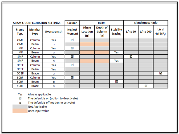
В зависимости от типа системы SFRS и типа стержня, выбранных для каждой конфигурации, необходимо учесть различные настройки и исходные данные. Данные опции представлены в таблице ниже (рисунок 3). Тип стержня «Сжатая диагональ» зарезервирован для многоуровневых жёстких рам (будущие версии).
Коэффициент сверхпрочности
Коэффициент сверхпрочности Ωo представляет собой коэффициент усиления, применяемый к силам в определенных элементах, через которые передается сейсмическая нагрузка. Цель состоит в том, чтобы предотвратить возникновение слабой связи до полного рассеивания энергии и достижения потенциальной пластичности первичной системы SFRS.
Например, для того, чтобы диагональная связь в стальной раме могла регулировать текучесть и рассеивать энергию, все остальные элементы на пути нагружения (например, соединения, колонны и коллекторы) должны быть прочнее максимальной ожидаемой прочности связи. Поэтому расчет данных элементов основан на увеличенной нагрузке с применением коэффициента сверхпрочности.
Коэффициенты сверхпрочности можно задать в основных данных. Более подробную информацию вы найдете в технической статье:
faq | Как включить коэффициенты повышения прочности Ωo в сочетания нагрузок по ASCE 7?
.
При установке флажка «включить сейсмическую нагрузку со сверхпрочностью», в сочетаниях нагрузок учитываются коэффициенты сверхпрочности. В результате стержень рассчитывается с повышенными нагрузками. Колонны всегда должны быть рассчитаны с повышенными нагрузками. Именно поэтому функция деактивации в программе не отображается. То же самое относится к балкам в OCBF.
Прочность колонны (опция пренебрежения моментом)
Все колонны в устойчивой к сейсмической нагрузке системе (SFRS) должны быть рассчитаны со сверхпрочностными нагрузками. Во многих случаях нет необходимости сочетать увеличенную нормальную силу с одновременными изгибающими моментами. Опция пренебрежения всеми изгибающими моментами, сдвигом и кручением в колоннах для предельного состояния по сверхпрочности активирована по умолчанию.
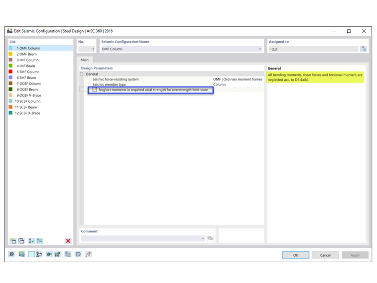
Для стандартных сочетаний нагрузок без увеличения прочности от воздействия сейсмической нагрузки проверяется комбинированное нагружение по AISC, глава H. Для сочетаний нагрузок со сверхпрочностью проверка по главе H опускается в случае, если выбрана опция «пренебречь моментами». По норме AISC 341 [1] необходимо проверить как типичные сочетания нагрузок, так и сочетания нагрузок со сверхпрочностью. This is shown in Example 4.3.2 of the AISC seismic design manual [2].
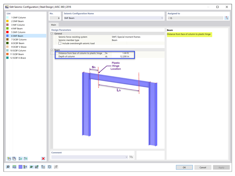
Расположение пластического шарнира
Расположение пластического шарнира Sh и ширина колонны dc используются для определения требуемой прочности на изгиб и сдвиг для соединения балка-колонна.
Придание жесткости для устойчивости балок
Связи устойчивости необходимы для балок в системах IMF и SRF для ограничения потери устойчивости плоской формы изгиба. В SCBF это требование применяется к балкам с V-образными или перевернутыми V-образными рамами.
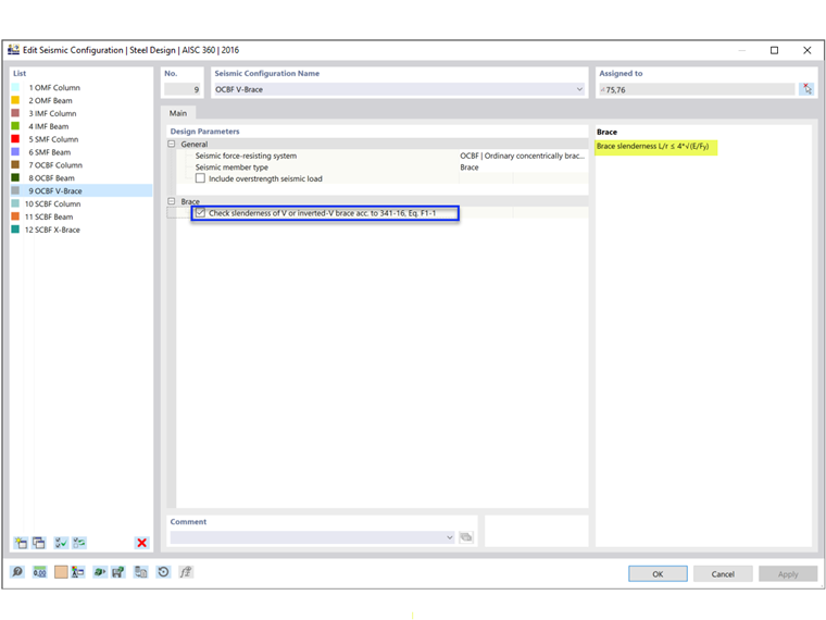
Коэффициент гибкости
Норма AISC 341 требует более надежного коэффициента гибкости для колонн в системе SMF, связей с V-образной или перевернутой V-образной связью в каркасе OCBF и всех связей в каркасе SCBF. Как показано на рисунке 3, пользователь может отключить функцию выполнения данных требований.
Тип расчетной ситуации и тип предельного состояния
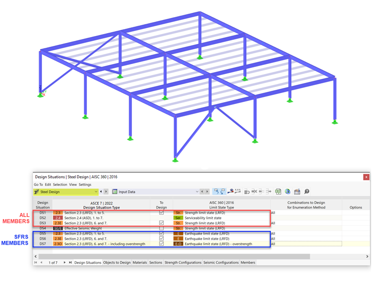
Для учета сейсмических нагрузок необходимо добавить тип расчетной ситуации, который включает в себя сочетания сейсмических нагрузок. Особое внимание необходимо уделить применению определенного типа предельного состояния.
Сейсмический расчет по AISC 341 выполняется только в том случае, если в качестве типа предельного состояния выбрано предельное состояние по сейсмике. Только стержни с присвоенной сейсмической конфигурацией рассчитываются для всех трех типов предельного состояния: Прочность, Сейсмика и Сейсмика (сверхпрочность). Все остальные стержни, которые не являются частью системы SFRS, рассчитаны в предельном состоянии по прочности.
Для проверки предельного прогиба используется предельное состояние по пригодности к эксплуатации, которое может быть, при необходимости, деактивировано пользователем.
More details on Design Situation can be found in the technical article: faq | Какие типы предельного состояния применимы в сейсмическом расчете по норме AISC 341? .