Список
Все загружения (ЗГ) модели перечислены слева от вкладки «Загружения». Здесь вы можете создать новый ЗГ, скопировать или удалить его. Другие функции, доступные с помощью кнопок в конце списка, описаны в таблице ниже.
|
|
Создает новое загружение. |
|
|
Копирует выбранные загружения |
|
|
Добавляет нагрузки к новому или существующему загружению |
|
|
Выбрать все загружения |
|
|
Инвертирует выбор загружений в списке |
Предпочтения
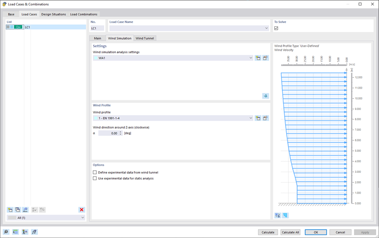
В этой области придайте «Параметры расчета моделирования воздействий ветра» ( WA ) к выбранному загружению.
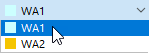
Вы можете выбрать «WA» из списка или создать новый тип настроек расчета моделирования воздействий ветра с помощью
![]() изменить Чтобы изменить выбранные параметры расчета моделирования воздействий ветра, нажмите
изменить Чтобы изменить выбранные параметры расчета моделирования воздействий ветра, нажмите
![]() изменить Диалоговое окно «Параметры расчета моделирования воздействий ветра» описано в разделе Параметры расчета моделирования воздействий ветра.
изменить Диалоговое окно «Параметры расчета моделирования воздействий ветра» описано в разделе Параметры расчета моделирования воздействий ветра.
Расчёт в RWIND 2
Также можно запустить RWIND 2 с помощью кнопки
![]() кнопка в правом углу области «Настройки». Эта функция позволяет экспортировать данные модели, относящиеся к одному из загружений, в программу RWIND 2.
кнопка в правом углу области «Настройки». Эта функция позволяет экспортировать данные модели, относящиеся к одному из загружений, в программу RWIND 2.
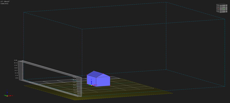
Здесь вы можете проверить настройки аэродинамической трубы, сетки, упрощения модели и т.д. При необходимости, можно настроить параметры. Ниже приводим общий пример:
- Запустите расчет RWIND 2.
- Проверьте результаты.
- Закройте RWIND 2 и вернитесь в RFEM 6/RSTAB 9.
- Рассчитайте оставшиеся загружения, если это применимо.
- Проверьте импортированные нагрузки в рабочем окне и в таблицах.
- Объедините ветровую нагрузку с другими загружениями в сочетаниях нагрузок и расчетных сочетаниях, если это применимо.
- Наконец, начнем расчет деформаций и внутренних сил.
Дополнительную информацию вы найдете в статье Базы знаний.
Важный
#iКнопка mage
![]() или все ЗГ
или все ЗГ
![]() .
.
профиль ветра
В этой области придайте «профиль ветра» выбранному загружению. Вы можете создать новый профиль ветра, щелкнув на
![]() изменить Чтобы изменить выбранный профиль ветра,
изменить Чтобы изменить выбранный профиль ветра,
![]() изменить Диалоговое окно «Профиль ветра» описано в разделе «Профиль ветра».
изменить Диалоговое окно «Профиль ветра» описано в разделе «Профиль ветра».
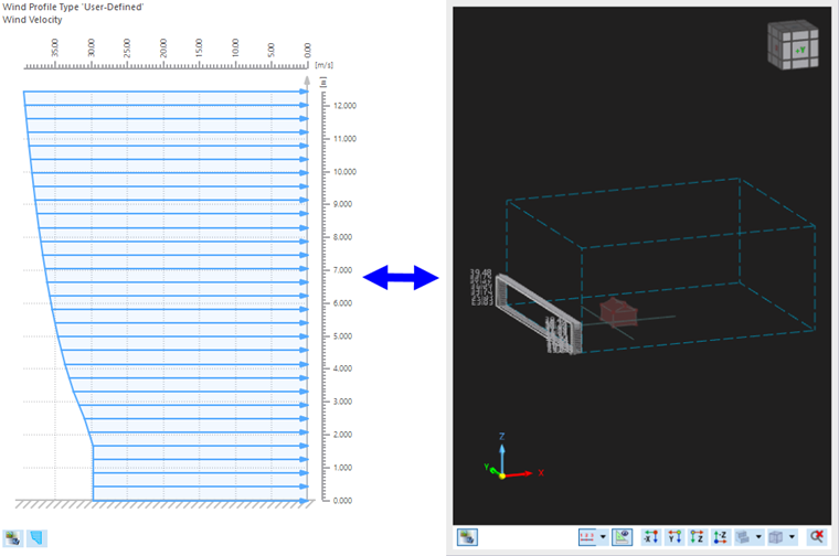
Профиль ветра отображается в правой части окна. Вы можете переключаться между профилем скорости и профилем интенсивности турбулентности с помощью
![]() изменить The
изменить The
![]() позволяет переключаться между отображением профиля ветра и отображением в аэродинамической трубе.
позволяет переключаться между отображением профиля ветра и отображением в аэродинамической трубе.
">image030023