Lista
Po lewej stronie zakładki „Przypadki obciążeń” wyświetlane są wszystkie przypadki obciążeń (PO) modelu. W tym miejscu można utworzyć nowe PO, skopiować je lub usunąć. Pozostałe funkcje dostępne za pomocą przycisków na końcu listy są opisane w poniższej tabeli.
|
|
Służy do tworzenia nowego przypadku obciążenia |
|
|
Kopiuje wybrane przypadki obciążeń |
|
|
Dodaje obciążenia do nowego lub istniejącego przypadku obciążenia |
|
|
Służy do zaznaczania wszystkich przypadków obciążeń |
|
|
Odwraca wybór przypadków obciążeń na liście |
Ustawienia i opcje
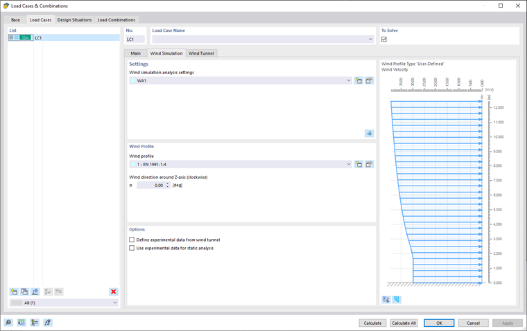
W tym obszarze należy przydzielić 'Ustawienia analizy symulacji wiatru' ( WA ) do wybranego przypadku obciążenia.
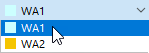
Można wybrać "WA" z listy lub utworzyć nowy typ ustawień analizy symulacji wiatru za pomocą
![]() edytować. Aby edytować wybrane ustawienia analizy symulacji wiatru, należy kliknąć
edytować. Aby edytować wybrane ustawienia analizy symulacji wiatru, należy kliknąć
![]() edytować. Okno dialogowe "Ustawienia analizy symulacji wiatru" jest opisane w rozdziale Ustawienia analizy symulacji wiatru.
edytować. Okno dialogowe "Ustawienia analizy symulacji wiatru" jest opisane w rozdziale Ustawienia analizy symulacji wiatru.
Obliczenia w RWIND 2
RWIND 2 można również uruchomić, klikając przycisk
![]() w prawym rogu obszaru „Ustawienia”. Funkcja ta eksportuje dane modelu dotyczące jednego z przypadków obciążeń do programu RWIND 2.
w prawym rogu obszaru „Ustawienia”. Funkcja ta eksportuje dane modelu dotyczące jednego z przypadków obciążeń do programu RWIND 2.
Można tam przeglądać ustawienia tunelu aerodynamicznego, siatki, uproszczenia modelu itp. W razie potrzeby parametry można dostosować. Oto przykład typowej procedury:
- Rozpocznij obliczenia RWIND 2.
- Sprawdź wyniki.
- Zamknij RWIND 2 i wróć do programu RFEM 6/RSTAB 9.
- W razie potrzeby można obliczyć pozostałe przypadki obciążeń.
- Sprawdź importowane obciążenia w oknie roboczym i w tabelach.
- W razie potrzeby należy połączyć przypadki obciążenia wiatrem z innymi przypadkami obciążeń w kombinacjach obciążeń i wyników.
- Na koniec rozpocznij obliczenia odkształceń i sił wewnętrznych.
Więcej informacji można znaleźć w artykule w Bazie informacji.
Ważne
#iPrzycisk mage
![]() lub wszystkie PO
lub wszystkie PO
![]() .
.
profil wiatru
W tym obszarze należy przydzielić 'Profil wiatru' do wybranego przypadku obciążenia. Nowy profil wiatru można utworzyć, klikając przycisk
![]() edytować. Wybrany profil wiatru można edytować za pomocą funkcji
edytować. Wybrany profil wiatru można edytować za pomocą funkcji
![]() edytować. Okno dialogowe "Profil wiatru" jest opisane w rozdziale Profil wiatru.
edytować. Okno dialogowe "Profil wiatru" jest opisane w rozdziale Profil wiatru.
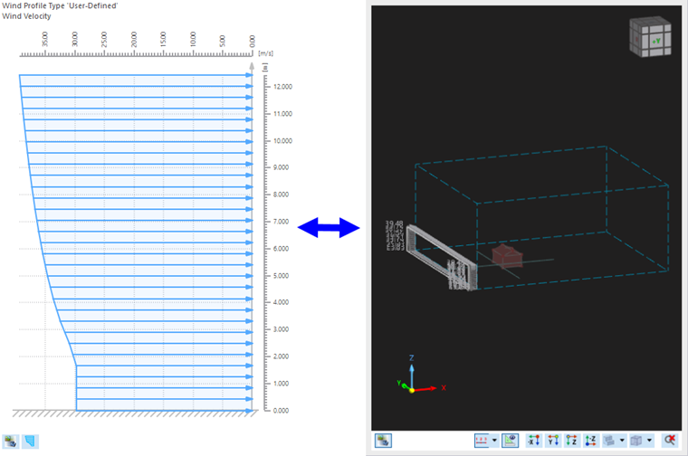
Profil wiatru wyświetlany jest w prawej części okna. Można przełączać między profilem prędkości a profilem intensywności turbulencji za pomocą przycisku
![]() edytować. The
edytować. The
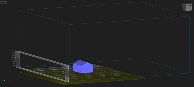
![]() umożliwia przełączanie między wyświetlaniem Profilu wiatru i tunelu aerodynamicznego.
umożliwia przełączanie między wyświetlaniem Profilu wiatru i tunelu aerodynamicznego.
">image030023