Elenco
Tutti i casi di carico (LC) del modello sono elencati a sinistra della scheda "Casi di carico". Lì, è possibile creare un nuovo CC, copiarlo o eliminarlo. Le altre funzioni disponibili dai pulsanti alla fine dell'elenco sono descritte nella tabella seguente.
|
|
Crea un nuovo caso di carico |
|
|
Copia i casi di carico selezionati |
|
|
Aggiunge carichi a un caso di carico nuovo o esistente |
|
|
Seleziona tutti i casi di carico |
|
|
Inverte la selezione dei casi di carico nell'elenco |
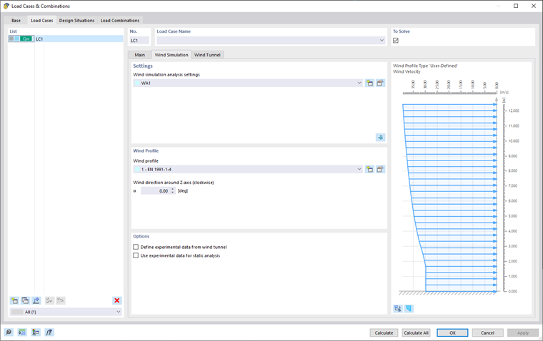
Impostazioni
In quest'area, assegnare le "Impostazioni dell'analisi della simulazione del vento" ( WA ) al caso di carico selezionato.
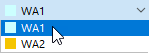
È possibile selezionare "WA" dall'elenco o creare un nuovo tipo di impostazioni per l'analisi della simulazione del vento utilizzando il
![]() per modificare. Per modificare le impostazioni dell'analisi della simulazione del vento selezionate, fare clic su
per modificare. Per modificare le impostazioni dell'analisi della simulazione del vento selezionate, fare clic su
![]() per modificare. La finestra di dialogo "Impostazioni dell'analisi della simulazione del vento" è descritta nel capitolo Impostazioni dell'analisi della simulazione del vento.
per modificare. La finestra di dialogo "Impostazioni dell'analisi della simulazione del vento" è descritta nel capitolo Impostazioni dell'analisi della simulazione del vento.
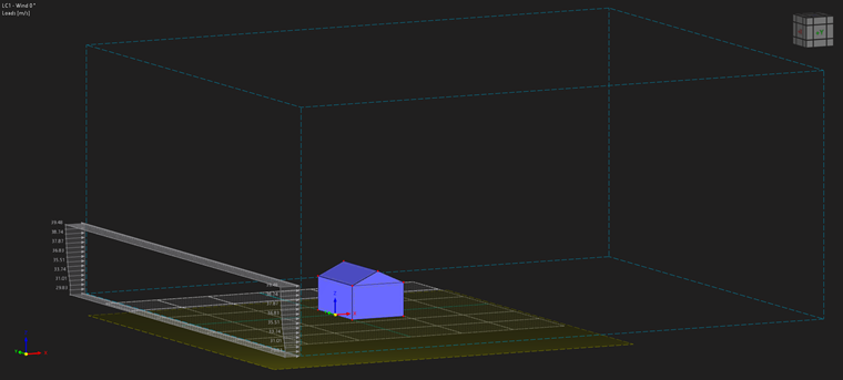
Calcolo in RWIND 2
È anche possibile avviare RWIND 2 facendo clic su
![]() nell'angolo destro dell'area "Impostazioni". Questa funzione esporta i dati del modello relativi a uno dei casi di carico nel programma RWIND 2.
nell'angolo destro dell'area "Impostazioni". Questa funzione esporta i dati del modello relativi a uno dei casi di carico nel programma RWIND 2.
Lì, è possibile rivedere le impostazioni della galleria del vento, la mesh, la semplificazione del modello e così via. Se necessario, è possibile modificare i parametri. Ecco un esempio di una procedura comune:
- Avvia il calcolo di RWIND 2.
- Controlla i risultati.
- Uscire da RWIND 2 e tornare a RFEM 6/RSTAB 9.
- Calcola i casi di carico rimanenti, se applicabile.
- Ispeziona i carichi importati nella finestra di lavoro e nelle tabelle.
- Combina i casi di carico del vento con altri casi di carico nelle combinazioni di carico e di risultati, se applicabile.
- Infine, inizia il calcolo degli spostamenti generalizzati e delle forze interne.
Trova ulteriori informazioni in un articolo di Knowledge Base.
Importante
The #iIl pulsante mage
![]() o tutti i CC
o tutti i CC
![]() .
.
profilo del vento
In quest'area, assegnare il "Profilo del vento" al caso di carico selezionato. È possibile creare un nuovo profilo del vento facendo clic su
![]() per modificare. Per modificare il profilo del vento selezionato, utilizzare il
per modificare. Per modificare il profilo del vento selezionato, utilizzare il
![]() per modificare. La finestra di dialogo "Profilo del vento" è descritta nel capitolo Profilo del vento.
per modificare. La finestra di dialogo "Profilo del vento" è descritta nel capitolo Profilo del vento.
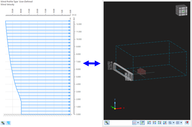
Il profilo del vento è visualizzato nella parte destra della finestra. È possibile passare dal profilo di velocità al profilo di intensità della turbolenza utilizzando il
![]() per modificare. Il
per modificare. Il
![]() consente di passare dalla visualizzazione del profilo del vento alla visualizzazione della galleria del vento.
consente di passare dalla visualizzazione del profilo del vento alla visualizzazione della galleria del vento.
">image030023