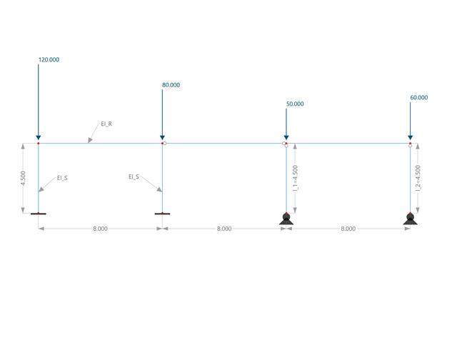
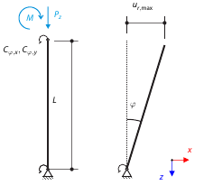
Este exemplo compara os comprimentos efetivos e o fator de carga crítica, que podem ser calculados no RFEM 6 utilizando o módulo Estabilidade da estrutura, com um cálculo manual. A estrutura é um pórtico encastrado com dois pilares biarticulados adicionais. Este pilar está sujeito a cargas concentradas verticais.
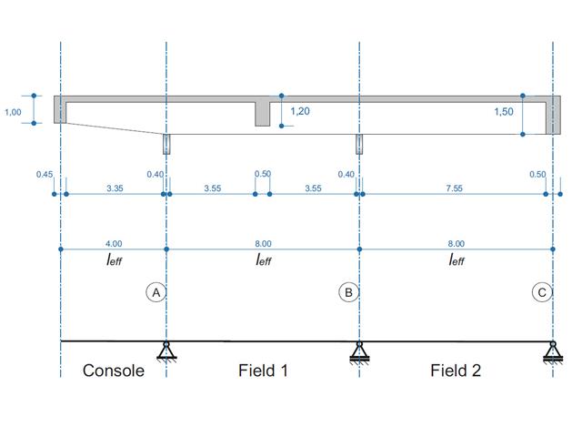
Uma viga de betão armado foi dimensionada como viga de dois vãos em consola. A secção é variável ao longo do comprimento da consola (secção de secção variável). São calculados os esforços internos, assim como a armadura longitudinal e transversal necessária para o estado limite último.
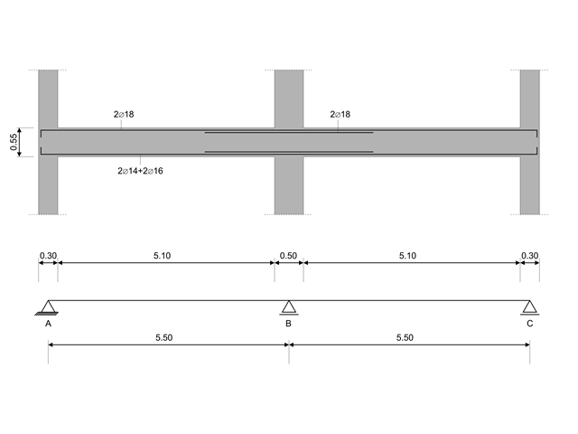
Neste exemplo de verificação, os valores de cálculo da capacidade das forças de corte nas vigas são calculados de acordo com EN 1998-1, 5.4.2.2 e 5.5.2.1, bem como os valores de cálculo da capacidade dos pilares fletidos de acordo com 5.2.3.3(2 ) O sistema é constituído por uma viga de betão armado de dois vãos com um comprimento de vão de 5,50 m. A viga faz parte de um sistema de pórtico. Os resultados obtidos são comparados com os em {%>
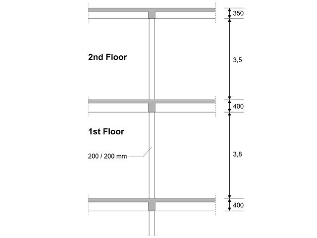
Foi dimensionado um pilar interior no primeiro andar de um edifício de três andares. O pilar é monolítico em relação à viga superior e inferior. O método A simplificado de dimensionamento ao fogo para pilares de acordo com o EC2-1-2 é verificado e os resultados comparados com {%>
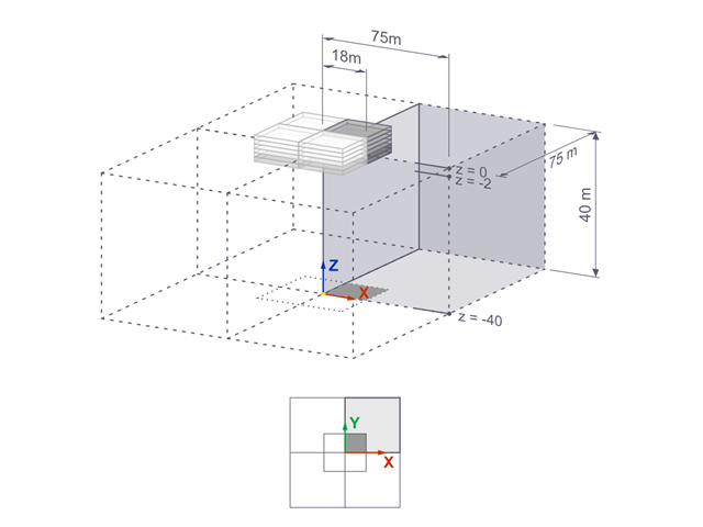
Os recalques de uma fundação rígida quadrada sobre uma argila lacustre [1] são calculados com o RFEM. Um quarto da fundação é modelado. A fundação tem uma largura de 75,0 m em ambos os lados. As fases de construção são utilizadas para gerar os resultados.
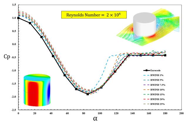
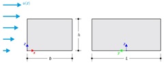
As normas disponíveis, como a EN 1991-1-4 [1], a ASCE/SEI 7-16 e a NBC 2015, apresentavam parâmetros de carga de vento, tais como coeficiente de pressão do vento (Cp ) para formas básicas. O importante é como calcular os parâmetros da carga de vento mais rapidamente e com mais precisão, em vez de trabalhar com fórmulas demoradas e por vezes complicadas em normas.
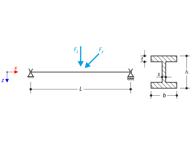
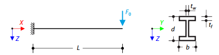
Nos apoios da forquilha está integrada uma estrutura constituída por um perfil em I. The axial rotation is restricted on both ends while warping is enabled. The structure is loaded by two transverse forces in the middle. The verification example is based on the example introduced by Gensichen and Lumpe.
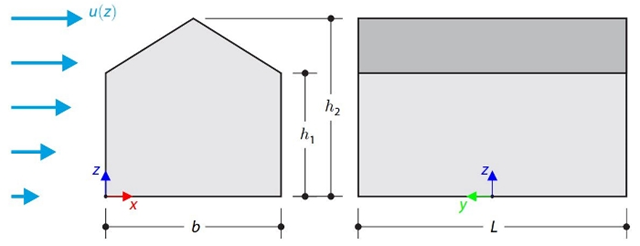
This verification example compares wind load calculations on a duopitch roof building using the ASCE 7-16 standard and using CFD simulation in RWIND Simulation. O edifício é definido conforme o esboço e o perfil da velocidade do fluxo contido na norma ASCE 7-16.
This verification example compares wind load calculations on a flat roof building using the ASCE 7-16 standard and using CFD simulation in RWIND Simulation. O edifício é definido conforme o esboço e o perfil da velocidade do fluxo contido na norma ASCE 7-16.
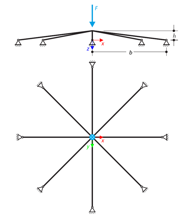
Uma estrutura plana simétrica é constituída por oito treliças idênticas encastradas em apoios articulados. The structure is loaded by a concentrated force and alternatively by imposed nodal deformation over the critical limit point when the snap-through occurs. Imposed nodal deformation is used in RFEM 5 and RSTAB 8 to obtain the full equilibrium path of the snap-through. The self-weight is neglected in this example. Determine the relationship between the actual loading force and the deflection, considering large deformation analysis. Evaluate the load factor at the given deflections.
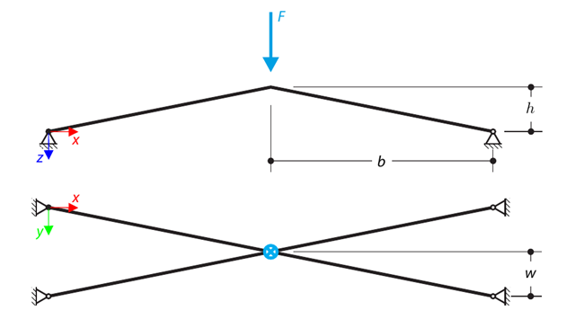
Uma estrutura é constituída por quatro treliças encastradas em apoios articulados. The structure is loaded by a concentrated force and alternatively by imposed nodal deformation over the critical limit point, when snap-through occurs. Imposed nodal deformation is used in RFEM 5 and RSTAB 8 to obtain the full equilibrium path of the snap-through. The self-weight is neglected in this example. Determine the relationship between the actual loading force and the deflection, considering large deformation analysis. Evaluate the load factor at given deflections.
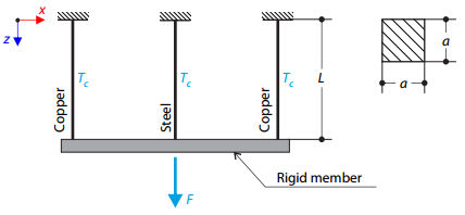
A truss structure consists of three rods (one steel and two copper) joined by a rigid member. The structure is loaded by a concentrated force and a temperature difference. Determine a flecha total da estrutura, sem considerar o peso próprio.
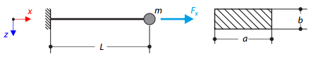
A cantilever of rectangular cross‑section has a mass at the end. Além disso, é carregada por uma força axial. Calculate the natural frequency of the structure. Neglect the self‑weight of the cantilever and consider the influence of the axial force for the stiffness modification.
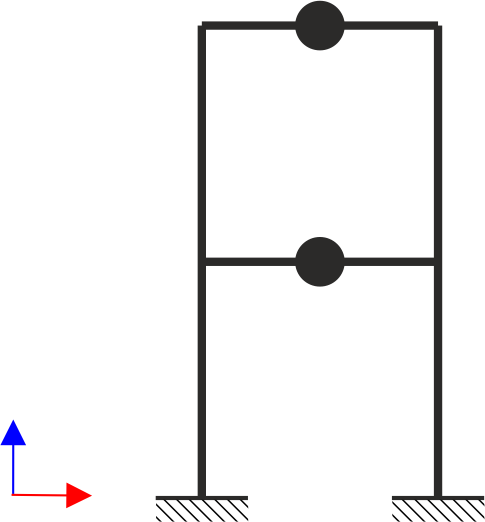
A estrutura de pórticos de dois pisos está sujeita a cargas sísmicas. The modulus of elasticity and cross‑section of the frame beams are much larger than those of the columns, so the beams can be considered rigid. The elastic response spectrum is given by the standard SIA 261/1:2003. Neglecting self-weight and assuming the lumped masses are at the floor levels, determine the natural frequencies of the structure. For each frequency obtained, specify the standardized displacements of the floors as well as equivalent forces generated using the elastic response spectrum according to the standard SIA 261/1.2003.
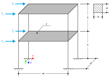
Este exemplo serve para ilustrar o plano. The application is shown on a two-story structure. The structure is loaded by means of lateral forces according to Figure 1. Determine the maximum deflection of the structure ux in the direction of the loading forces using both the diaphragm constraint and the plate model of the floor.
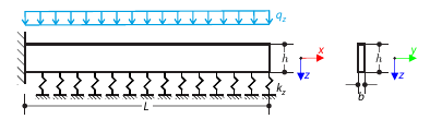
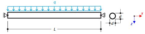
Sobre uma fundação elástica Pasternak, encontra-se uma viga em consola com uma secção retangular que está sujeita a uma carga distribuída. The image shows the calculation of the maximum deflection and maximum bending moment.
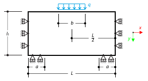
Uma alvenaria está sujeita a uma carga distribuída a meio da secção superior. The Isotropic Masonry 2D material model is compared with the Isotropic Linear Elastic model, with surface stiffness property Without Tension in the nonlinear calculation.
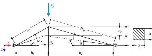
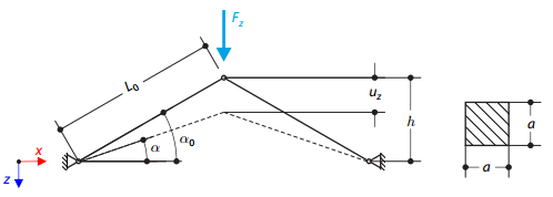
O modelo da estrutura é constituído por duas treliças de comprimento desigual que estão incorporadas nos apoios de articulação. The structure is loaded by concentrated force. The self-weight is neglected. Determine the relationship between the loading force and the deflection, considering large deformations.
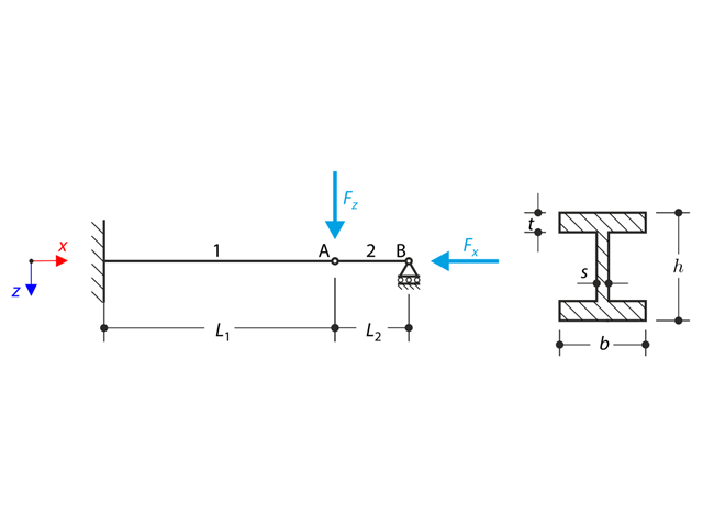
A structure made of an I-profile is fully fixed on the left end and embedded into the sliding support on the right end. A estrutura é constituída por dois segmentos. The self-weight is neglected in this example. Determine the maximum deflection of the structure, the bending moment on the fixed end, the rotation of segment 2, and the reaction force at point B by means of the geometrically linear analysis and the second-order analysis. The verification example is based on the example introduced by Gensichen and Lumpe.
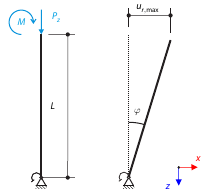
Imaginemos um tubo de andaime resistente à flexão fixado por um apoio nodal para andaimes na parte inferior e carregado por um momento e por uma força. Calculate the maximum deflection with consideration of initial slippage.
Imaginemos um tubo de andaime resistente à flexão fixado por um apoio nodal para andaimes na parte inferior e carregado por um momento e por uma força. Calculate the maximum radial deflection by exceeding the capacity of the scaffolding support.
Análise de histórico de tempo na viga em consola (sistema SDOF) excitada por uma função periódica. Vertical deformations and accelerations calculated with direct integration and modal analysis in RF‑/DYNAM Pro - Forced Vibrations are compared with the analytical solution.
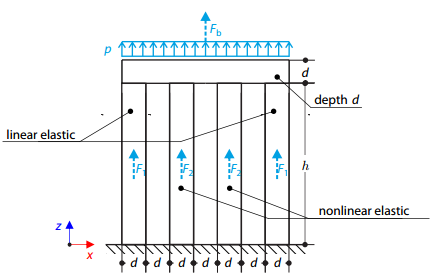
Quatro pilares estão fixados na parte inferior e ligados por um bloco rígido na parte superior. The block is loaded by pressure and modeled by an elastic material with a high modulus of elasticity. The outer columns are modeled by linear elastic material and the inner columns by a stress-strain diagram with decaying dependence. Assuming only the small deformation theory and neglecting the structure's self-weight, determine its maximum deflection.
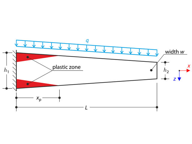
Uma viga de secção variável em consola está completamente fixada na extremidade esquerda e carregada por uma carga contínua. Plastic material is considered for the calculation.
Um cabo de aço ou uma membrana com pinos nas duas extremidades é carregado por uma carga distribuída. Neglecting its self-weight, determine the maximum deflection of the structure using the large deformation analysis.
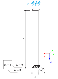
A vertical cantilever with a square cross-section is loaded at the top by tensile pressure. A consola é feita de um material isotrópico. Calculate the deflection.
O modelo da estrutura é constituído por duas vigas de treliça que estão incorporadas nos apoios de articulação. The structure is loaded by concentrated force. The self-weight is neglected. Determine the relationship between the loading force and the deflection, considering large deformations.
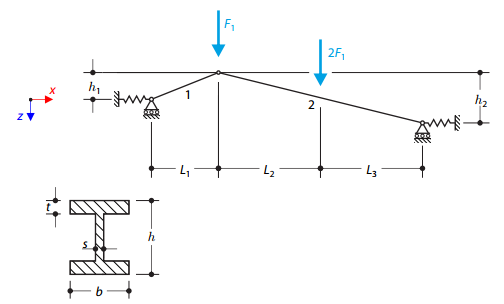
A structure made of I-profile trusses is supported on both ends by spring sliding supports and loaded by transversal forces. O peso próprio não é considerado neste exemplo. Determine the deflection of the structure, the bending moment, the normal force in the given test points, and the horizontal deflection of the spring supports.
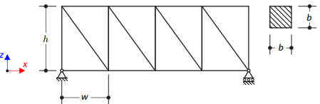
Uma treliça plana é apoiada de forma simples. The aim of this verification example is to determine the natural frequencies of the structure.
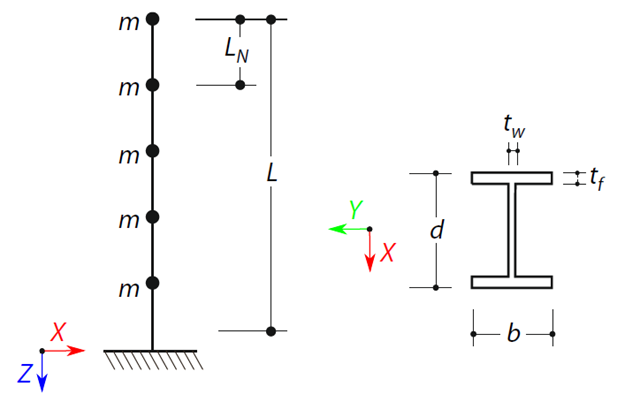
É definida uma viga em consola com uma secção de viga em I de comprimento L. The beam has five mass points with masses m acting in the X-direction. The self-weight is neglected. The frequencies, mode shapes, and equivalent loads of this 5-DOF system are analytically calculated and compared with the results from RSTAB and RFEM.