- Special Moment Frame (SMF)
- Intermediate Moment Frame (IMF)
- Ordinary Moment Frame (OMF)
- Ordinary Concentrically Braced Frame (OCBF)
- Special Concentrically Braced Frame (SCBF)
Seismic Configuration Input
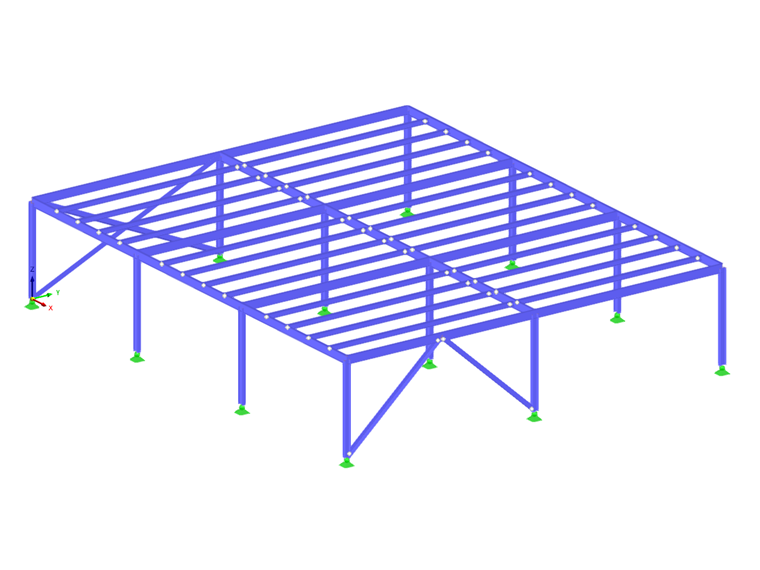
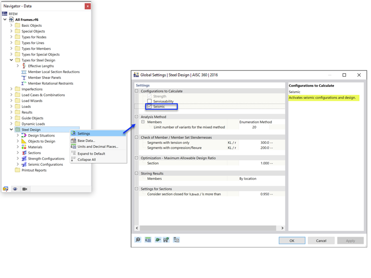
The relevant input for the design is defined in the Seismic Configuration. The Seismic Configuration can be activated in the Global Settings of the Steel Design folder (Image 1).
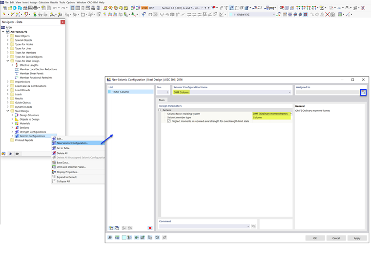
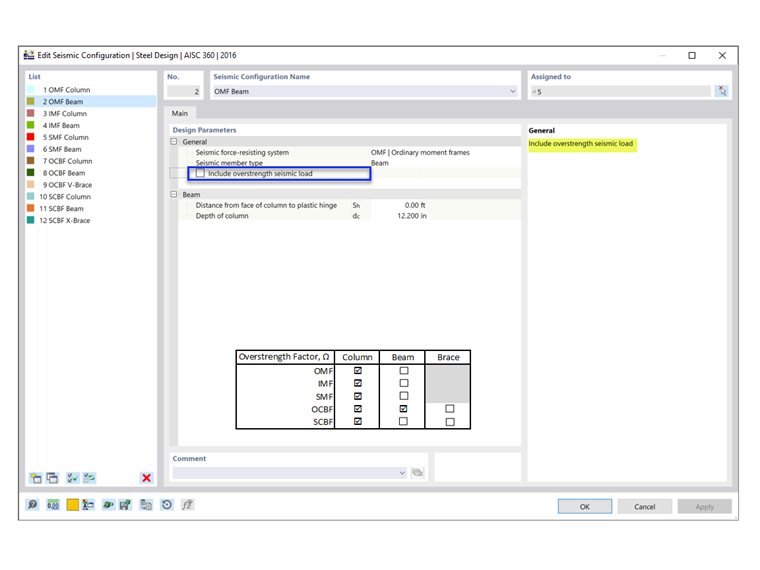
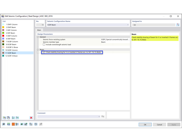
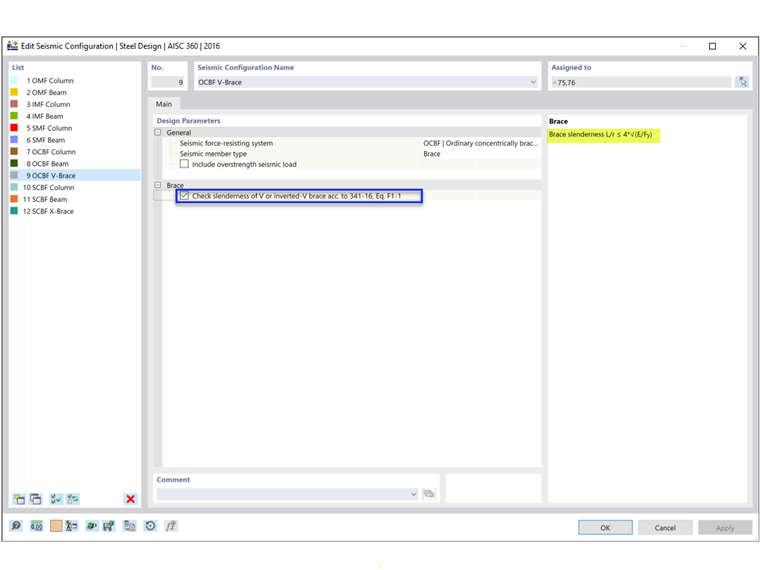
After doing so, a new Seismic Configuration can be defined by entering a descriptive configuration name, then selecting the SFRS frame type and member type (Image 2).
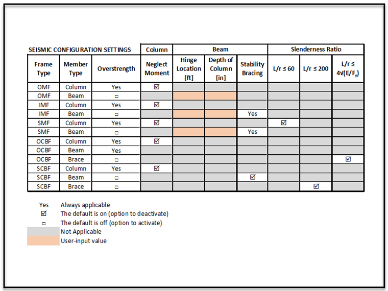
Various settings and inputs need to be considered depending on the SFRS type and member type selected for each configuration. These options are summarized in the table below (Image 3). The member type “Strut” is reserved for multi-tiered braced frames (future release).
Overstrength Factor
The overstrength factor, Ωo, is an amplification factor applied to the forces in certain elements in the seismic load path. The purpose is to prevent a weak link from occurring prior to the full energy dissipation and reaching the ductility potential of the primary SFRS.
For example, in order for the diagonal brace in a steel braced frame to yield and dissipate energy in a controlled manner, all other elements of the load path (for example, connections, columns, and collectors) need to be stronger than the maximum anticipated strength of the brace. Therefore, the design of those elements is based on the amplified loading using the overstrength factor.
The overstrength factors can be set in the Base Data. More details can be found in the technical article:
FAQ | How do I include the overstrength factor(s) Ωo in the ASCE 7 load combinations?
.
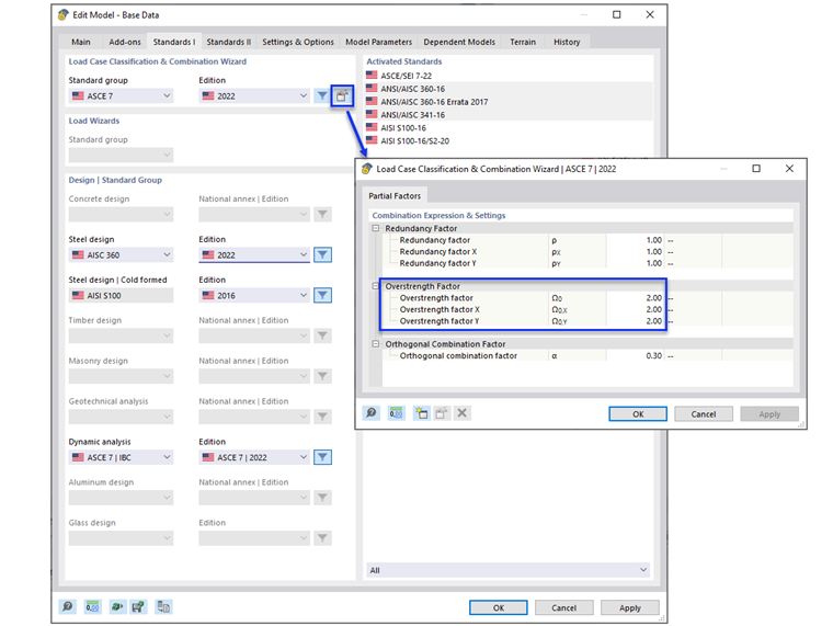
When the “Include overstrength seismic load” box is checked, the overstrength factors are considered in the load combinations. As a result, the member is designed with the amplified loads. The columns are always required to be designed with the amplified loads. Therefore, the option to deactivate is not shown. The same is true for beams in OCBF.
Column Strength (Neglect Moment Option)
All columns in a seismic force-resisting system (SFRS) are required to be designed with overstrength loads. In many cases, the amplified axial force does not need to be combined with the concurrent bending moments. The option to neglect all bending moments, shear, and torsion in columns for the overstrength limit state is activated by default.
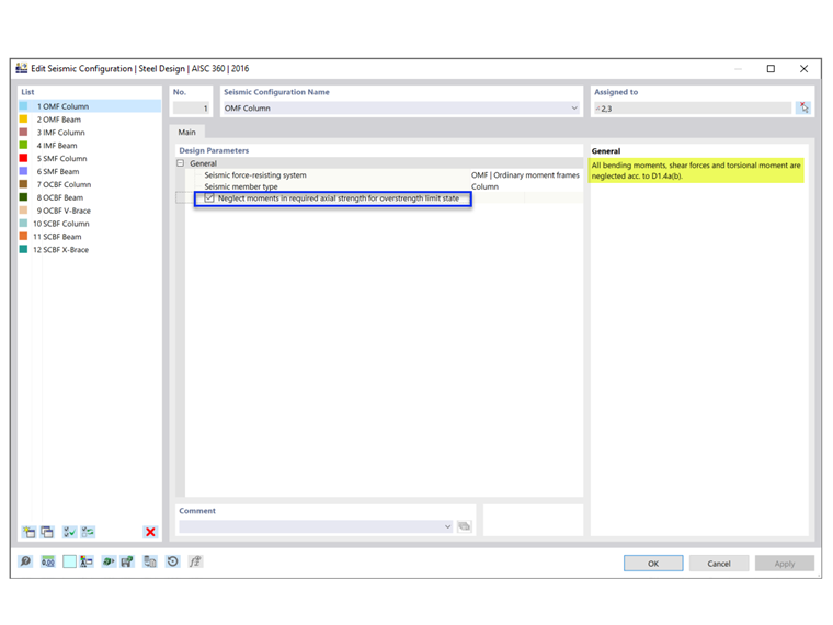
For standard load combinations without overstrength from seismic load effects, the combined loading according to AISC chapter H is checked. For overstrength load combinations, the Chapter H check is ignored when the "Neglect moments" option is selected. As per AISC 341 [1], both standard and overstrength load combinations must be checked. This is shown in Example 4.3.2 of the AISC seismic design manual [2].
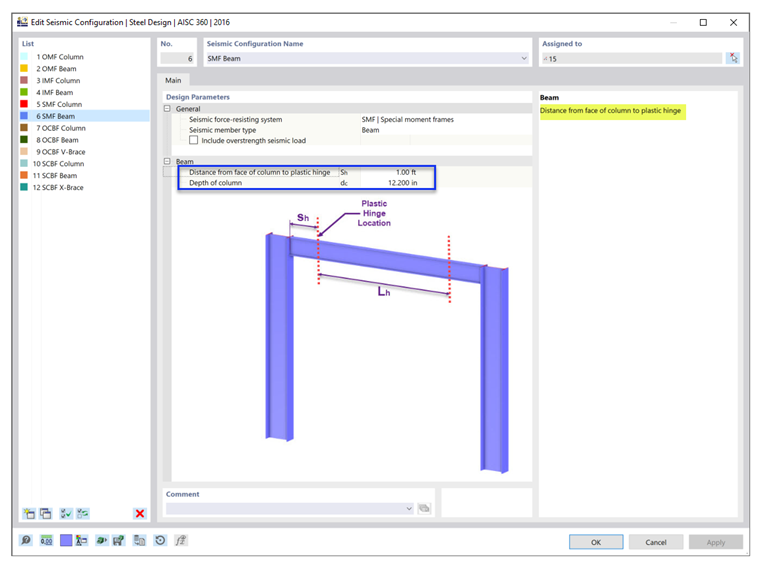
Plastic Hinge Location
The plastic hinge location, Sh, and the depth of the column, dc, are used to determine the required flexural and shear strength of the beam-to-column connection.
Stability Bracing of Beams
Stability bracing of beams is required for beams in IMF and SMF to restrain lateral-torsional buckling. In SCBF, this requirement is applicable to beams with V or inverted-V frames.
Slenderness Ratio
AISC 341 requires a more robust slenderness ratio for columns in SMF, braces with V or inverted-V configuration in OCBF, and all braces in SCBF. As summarized in Image 3, the option to meet these requirements can be deactivated by the user.
Design Situation Type & Limit State Type
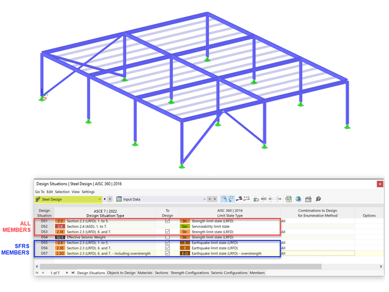
The Design Situation Type that includes seismic load combinations needs to be added to consider the seismic loads. Careful attention must be paid when applying the Limit State Type.
The AISC 341 seismic design is only performed when the Earthquake Limit State is selected as the limit state type. Only members with assigned Seismic Configuration are designed for all three limit state types: Strength, Earthquake, and Earthquake (overstrength). All other members that are not part of the SFRS are designed for the Strength Limit State.
The Serviceability Limit State is used to check for the deflection limit and can be deactivated by the user, if not needed.
More details on Design Situation can be found in the technical article: FAQ | Which limit state types are applicable for the AISC 341 seismic design? .