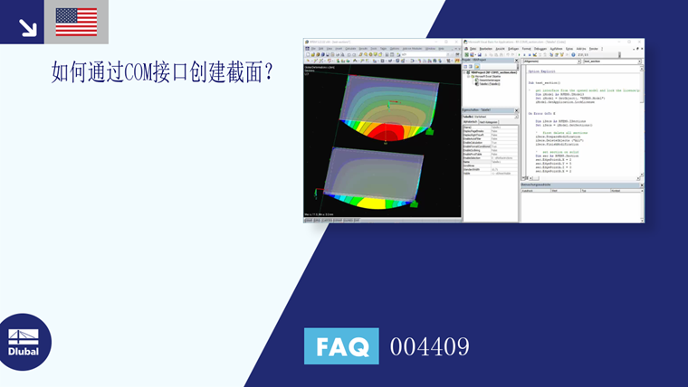
截面与杆件一样,是一种单元,其创建方法与杆件相同。 Zuerst wird die Schnittstelle zu den Objekten benötigt. Beim Stab wäre das IModelData, bei den Schnitten ist es ISections. Dieses Interface ist in IModel3 zu finden:
Sub test_section()
'   get interface from the opened model and lock the licence/program
    Dim iModel As RFEM5.IModel3
    Set iModel = GetObject(, "RFEM5.Model")
    iModel.GetApplication.LockLicense

On Error GoTo E

    Dim iSecs As RFEM5.ISections
    Set iSecs = iModel.GetSections()
Zunächst werden alle bereits angelegten Schnitte gelöscht und danach zwei neue Schnitte angelegt.
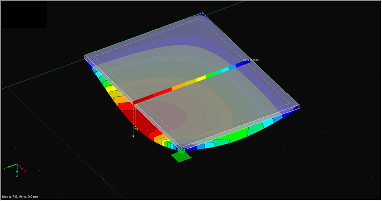
Der erste Schnitt soll ein Volumenschnitt mit sichtbarer Schnittfläche sein (siehe Bild 01). Die Eingabe erfolgt analog zur Eingabe in RFEM. Als Typ wird "SectionOnSectionalArea" gewählt, über "EdgePoint" werden die Eckpunkte des Schnittes gesetzt und "Vector" definiert die Richtung des Schnitts:
' first delete all sections
iSecs.PrepareModification
iSecs.DeleteObjects ("All")
iSecs.FinishModification
' set section on solid
Dim sec As RFEM5.Section
sec.EdgePointA.X = 2
sec.EdgePointA.Y = 5
sec.EdgePointA.Z = 0
sec.EdgePointB.X = 2
sec.EdgePointB.Y = 8
sec.EdgePointB.Z = 0
sec.no = 1
sec.Name = "solid section"
sec.Plane = GlobalPlaneInPositiveX
sec.ShowValuesInIsolines = False
sec.Type = SectionOnSolidSectionLine
sec.ObjectList = "1"
iSecs.PrepareModification
iSecs.SetSection sec
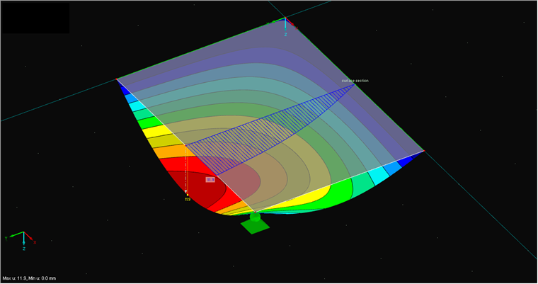
iSecs.FinishModificationWie bereits durch andere Elemente bekannt, wird der neue Schnitt schlussendlich in einem Prepare-/FinishModifikation-Block übergeben. Als zweiter Schnitt soll ein Flächenschnitt angelegt werden (siehe Bild 02). Dazu muss als Typ "SectionViaSurfacePlane" verwendet werden. Bei einem Flächenschnitt muss neben der Angabe des Vektors der Schnittrichtung auch die Darstellungsebene der Ergebnisse gewählt werden. Im folgenden Beispiel wird die xy-Ebene über das Einstellen von "GlobalPlaneInPositiveX" gewählt:
'   set section on surface
    sec.EdgePointA.X = 2
    sec.EdgePointA.Y = 0
    sec.EdgePointA.Z = 0
    sec.EdgePointB.X = 2
    sec.EdgePointB.Y = 3
    sec.EdgePointB.Z = 0

    sec.no = 2
    sec.Name = "surface section"
    sec.Plane = GlobalPlaneInPositiveX

    sec.ShowValuesInIsolines = True
    sec.Type = SectionViaSurfacePlane
    sec.ObjectList = "1"

    sec.Vector.X = 0
    sec.Vector.Y = 0
    sec.Vector.Z = 1

    iSecs.PrepareModification
    iSecs.SetSection sec
    iSecs.FinishModification
Die Ergebnisse eines Schnitts können ebenfalls über die gesonderte Methode "GetResultsInSection" der Schnittstelle "IResults2" geholt werden. Im Folgenden werden die Querkräfte am Flächenschnitt geholt. Der Verlauf der Schnittgrößen wird über "ContinuousDistributionWithinObjects" auf "Durchlaufend innerhalb Flächen" eingestellt:
 '   get results
    Dim iCalc As ICalculation2
    Set iCalc = iModel.GetCalculation

    Dim iRes As IResults2
    Set iRes = iCalc.GetResultsInFeNodes(LoadCaseType, 1)

    Dim secRes() As RFEM5.SectionResult
    secRes = iRes.GetResultsInSection(2, AtNo,
      ShearForceVy,ContinuousDistributionWithinObjects, False)
Im Anhang finden Sie das Excel-Makro und die Testdatei, um das Programm nachvollziehen zu können.