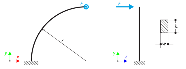
Una viga de un cuarto de círculo con una sección rectangular está cargada por medio de una fuerza fuera del plano. This force causes a bending moment, torsional moment, and transverse force. While neglecting self-weight, determine the total deflection of the curved beam.
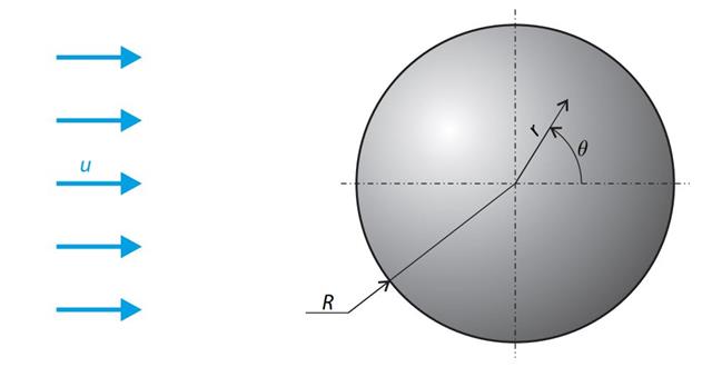
A sphere is subjected to a uniform flow of viscous fluid. The velocity of the fluid is considered at infinity. The goal is to determine the drag force. The parameters of the problem are set so that the Reynolds number is small and the radius of the sphere is also small, thus the theoretical solution can be reached - Stokes flow (G. G. Stokes 1851).
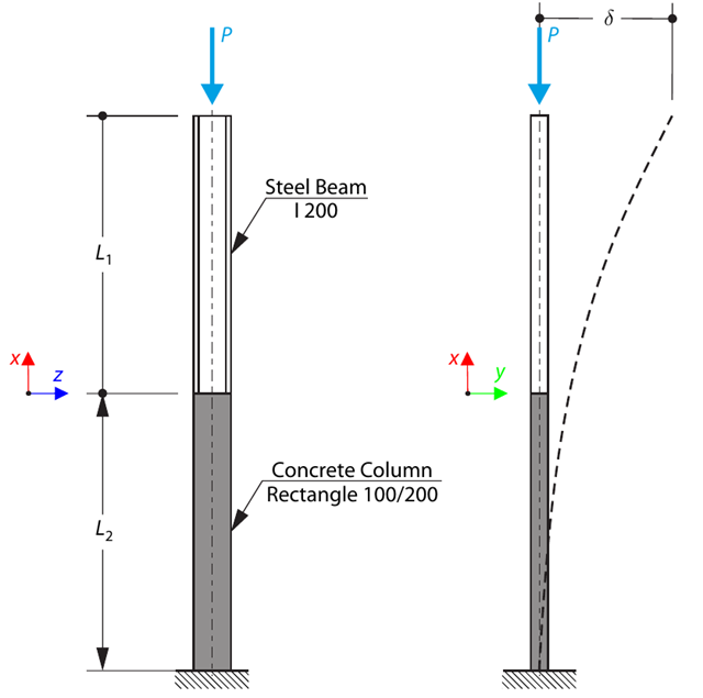
Un pilar se compone de una sección de hormigón (rectángulo 100/200) y una sección de acero (perfil I 200). It is subjected to pressure force. Determine the critical load and corresponding load factor. The theoretical solution is based on the buckling of a simple beam. In this case, two regions have to be taken into account due to different moments of inertia and material properties.
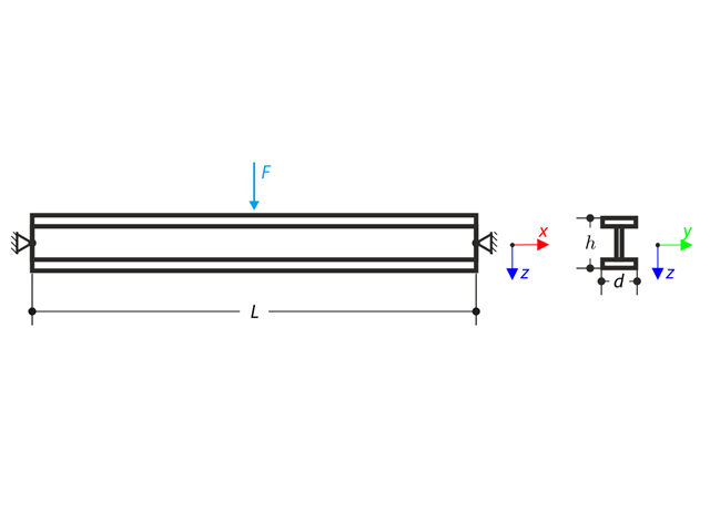
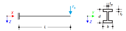
Una viga articulada en ambos extremos está cargada con una fuerza concentrada en el medio. Neglecting its self-weight and shear stiffness, determine the beam's maximum deflection, normal force, and moment at the mid-span, assuming the second- and third-order analysis.
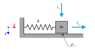
Un oscilador simple consta de una masa m (considerada solo en la dirección x) y un muelle lineal de rigidez k. The mass is embedded on a surface with Coulomb friction and is loaded by constant-in-time axial and transverse forces.
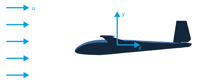
El objetivo de este ejemplo de verificación es analizar el flujo de fluidos alrededor de un planeador. La tarea consiste en determinar el coeficiente de arrastre y el coeficiente de sustentación con respecto al ángulo de incidencia. Estos coeficientes también se pueden dibujar en el gráfico de arrastre polar. El ángulo límite para el flujo de fluido laminar alrededor del perfil del ala también se puede determinar a partir del campo de velocidades. El modelo de CAD en 3D disponible (archivo STL) se utiliza en RWIND 2.
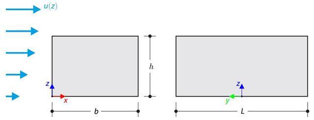
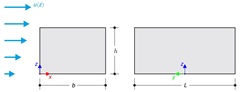
El ejemplo de verificación compara el cálculo de la carga de viento en un edificio con una cubierta plana utilizando la norma EN 1991-1-4 y utilizando la simulación CFD en RWIND Simulation. The building is defined according to the sketch, and the inflow velocity profile is taken according to the standard EN 1991-1-4.
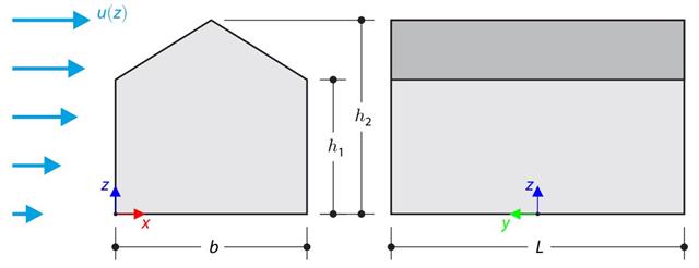
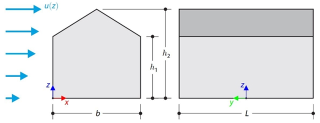
El ejemplo de verificación compara el cálculo de la carga de viento en un edificio con una cubierta a dos aguas utilizando la norma EN 1991-1-4 y utilizando la simulación CFD en RWIND Simulation. The building is defined according to the sketch, and the inflow velocity profile is taken according to the standard EN 1991-1-4.
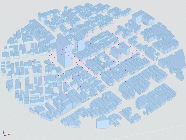
El Instituto de Arquitectura de Japón (AIJ) ha presentado una serie de escenarios de referencia bien conocidos de la simulación de viento.
El siguiente artículo gira en torno al "Caso E - un complejo de edificios en una zona urbana real con una densa concentración de edificios de poca altura en la ciudad de Niigata".
A continuación, se simula el escenario descrito en RWIND2 y se comparan los resultados con los resultados simulados y experimentales del AIJ.
Este ejemplo de verificación compara los cálculos de la carga de viento en un edificio con cubierta a dos aguas utilizando la norma ASCE 7-16 y utilizando la simulación CFD en RWIND Simulation. The building is defined according to the sketch and the inflow velocity profile taken from the ASCE 7-16 standard.
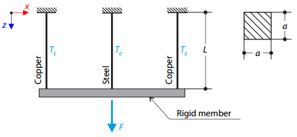
Una estructura de celosía consta de tres barras (una de acero y dos de cobre) unidas por una barra rígida. The structure is loaded by a concentrated force and a temperature difference. While neglecting self‑weight, determine the total deflection of the structure.
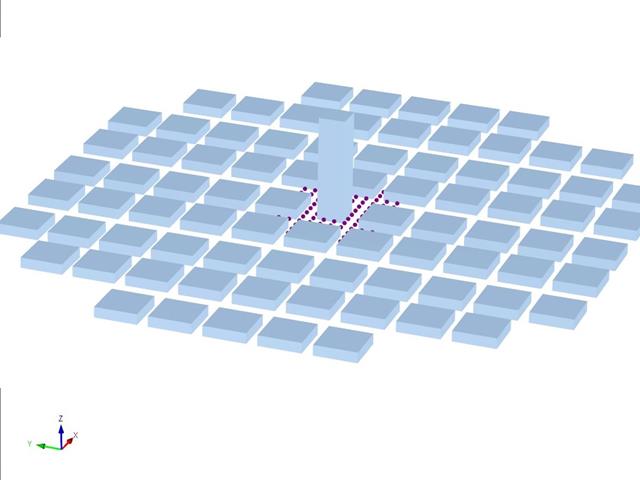
El Instituto de Arquitectura de Japón (AIJ) ha presentado una serie de escenarios de referencia bien conocidos de la simulación de viento.
El siguiente artículo trata del "Caso D - Edificio de gran altura entre manzanas".
A continuación, se simula el escenario descrito en RWIND2 y se comparan los resultados con los resultados simulados y experimentales del AIJ.
Este ejemplo de verificación compara los cálculos de la carga de viento en un edificio de cubierta plana utilizando la norma ASCE 7-16 y utilizando la simulación CFD en RWIND Simulation. The building is defined according to the sketch and the inflow velocity profile taken from the ASCE 7-16 standard.
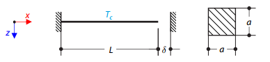
Una barra de acero entre dos apoyos rígidos con un espacio está cargada por una diferencia de temperatura. While neglecting self‑weight, determine the total deformation of the rod and its internal axial force.
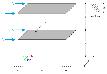
Este ejemplo sirve como demostración de la coacción del diafragma. The application is shown on a two-story structure. The structure is loaded by means of lateral forces according to Figure 1. Determine the maximum deflection of the structure ux in the direction of the loading forces using both the diaphragm constraint and the plate model of the floor.
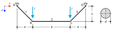
Una viga está completamente fija (el alabeo está restringido) en el extremo izquierdo y está apoyada en un apoyo en horquilla (el alabeo está habilitado) en el extremo derecho. The beam is subjected to a torque, longitudinal force, and transverse force. Determine the behavior of the primary torsional moment, secondary torsional moment, and warping moment. The verification example is based on the example introduced by Gensichen and Lumpe.
Un cable en la posición inicial está cargado por dos fuerzas concentradas. The self‑weight is neglected. Determine the normal forces in the cable.
Análisis en el dominio del tiempo de una viga en voladizo (sistema SDOF) excitada por una función periódica. Vertical deformations and accelerations calculated with direct integration and modal analysis in RF‑/DYNAM Pro - Forced Vibrations are compared with the analytical solution.
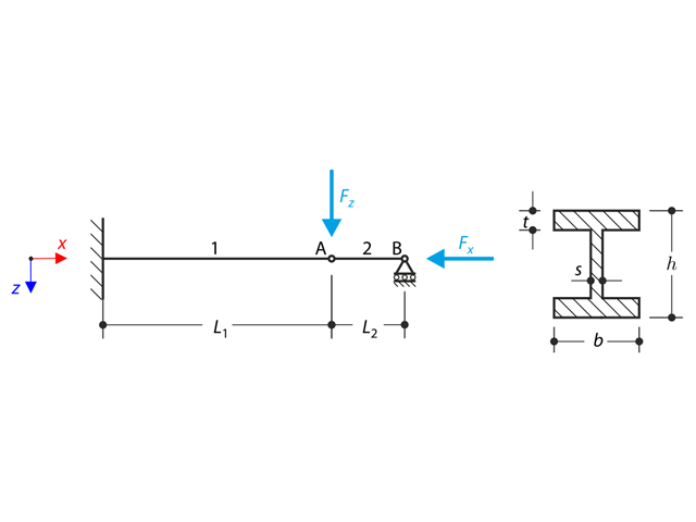
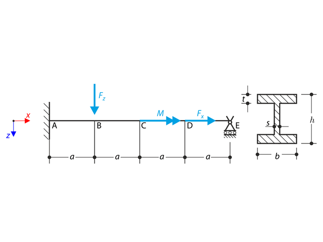
Una estructura hecha de un perfil en I está completamente fijada en el extremo izquierdo y empotrada en el apoyo deslizante en el extremo derecho. The structure consists of two segments. The self-weight is neglected in this example. Determine the maximum deflection of the structure, the bending moment on the fixed end, the rotation of segment 2, and the reaction force at point B by means of the geometrically linear analysis and the second-order analysis. The verification example is based on the example introduced by Gensichen and Lumpe.
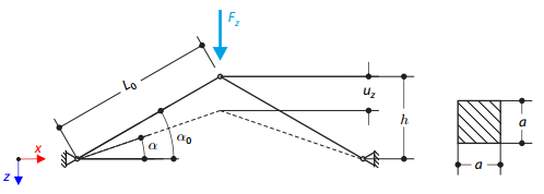
A structure is made of two trusses, which are embedded into the hinge supports. The structure is loaded by concentrated force. Se omite el peso propio. Determine the relationship between the loading force and the deflection, considering large deformations.