


В программе RFEM 6 можно использовать функцию «поперечные элементы жесткости стержня», с помощью которой можно добавить требуемые элементы жесткости по длине стержня. Повышенную прочность на сдвиг от элемента жёсткости можно учесть в аддоне Расчёт стальных конструкций.
Раздел AISC G2 «Двутавровые стержни и швеллеры» [1] состоит из трех частей:
- G2.1 Прочность на сдвиг стенок без действия области растяжения
- G2.2 Прочность на сдвиг внутренних панелей стенки с a/h ≤ 3, с учетом действия области растяжения
- G2.3 Поперечные элементы жесткости
Что такое действие области растяжения?
Действие области растяжения - это явление, при котором стенка составной балки рассчитывается таким образом, чтобы она имела высокую прочность после потери продольной устойчивости. Стенка в состоянии после потери продольной устойчивости все еще способна воспринимать приложенную нагрузку растяжения.
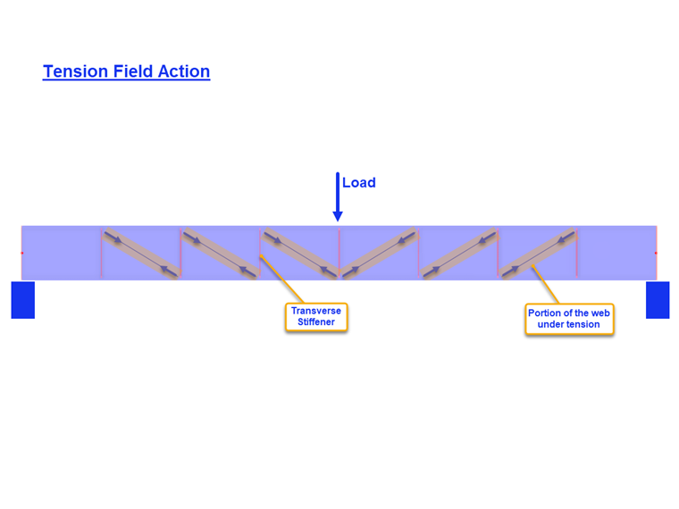
Действие растяжения можно учесть для внутренних панелей, только при условии, что a/h не превышает 3,0 (AISC, раздел G2.2), где a - расстояние между элементами жесткости в свету, а h - расстояние между полками в свету.
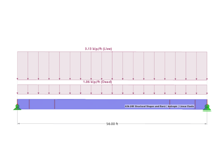
Пример
Для сравнения прочности на сдвиг, полученной по модели RFEM, здесь представлены примеры G.8A и G.8B из нормы AISC 2016 Design Examples [2]. Длина балки составляет 56 футов, высота 3 фута, толщина полки 1,5 дюйма, ширина полки 16 дюймов, а толщина стенки 5/16 дюйма. Сжатая полка непрерывно усилена связями, вследствие чего мы можем деактивировать в программе расчет потери устойчивости плоской формы изгиба.
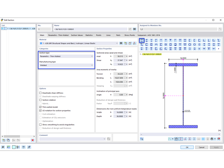
Составную балку можно создать с помощью сечения с типом «параметрическое - тонкостенное» и типом изготовления «сварное».
1) Проверьте, требуются ли поперечные элементы жесткости по AISC, раздел G2.3
Поперечные элементы жёсткости не требуются, если выполняется одно из следующих условий.
- h/tw меньше чем 2,46 √(E/Fy)
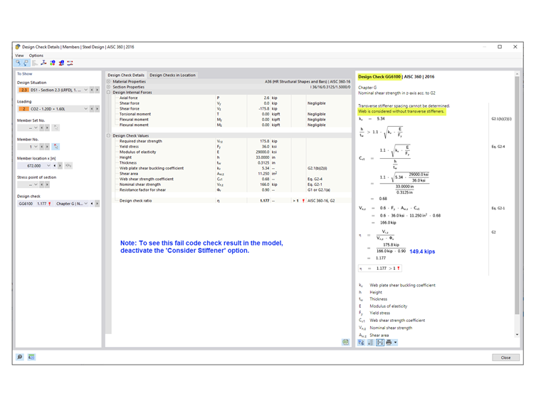
33,0 дюйм/0,3125 дюйм = 105,6, что больше, чем 2,46*√(29 000 кфунт/кв.дюйм /36 кфунт/кв.дюйм) = 69,82
- Требуемая прочность на сдвиг меньше фактической прочности. Как показано в расчете GG6100, требуемая прочность на сдвиг (175,8 кфунт) больше, чем фактическая прочность на сдвиг (149,4 кфунт).
- Поскольку ни одно из вышеперечисленных условий не выполняется, требуются поперечные элементы жёсткости.
2) Задайте расстояние между элементами жесткости
Таблицы 3-16a, 3-16b и 3-16c из руководства AISC по стальным конструкциям [3] помогут вам определить требуемое расстояние между элементами жесткости на основе соотношения h/tw и требуемого напряжения. В качестве альтернативы, можно применить итерационный метод проб и ошибок для определения расстояния.
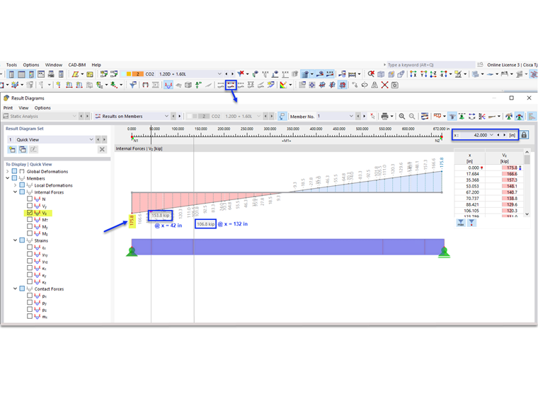
В нашем примере для торцевой панели задано расстояние 42 дюйма. Требуемую прочность на сдвиг в данной области можно легко определить с помощью инструмента «диаграмма результатов для выбранного стержня». На конце первой панели Vz = 153,8 кфунтов превышает фактическую прочность, равную 149,4 кфунтов. Поэтому необходимо добавить вторую панель размером 90. Третья панель не требуется, так как V = 106,8 кфунтов меньше, чем 149,4 кфунтов.
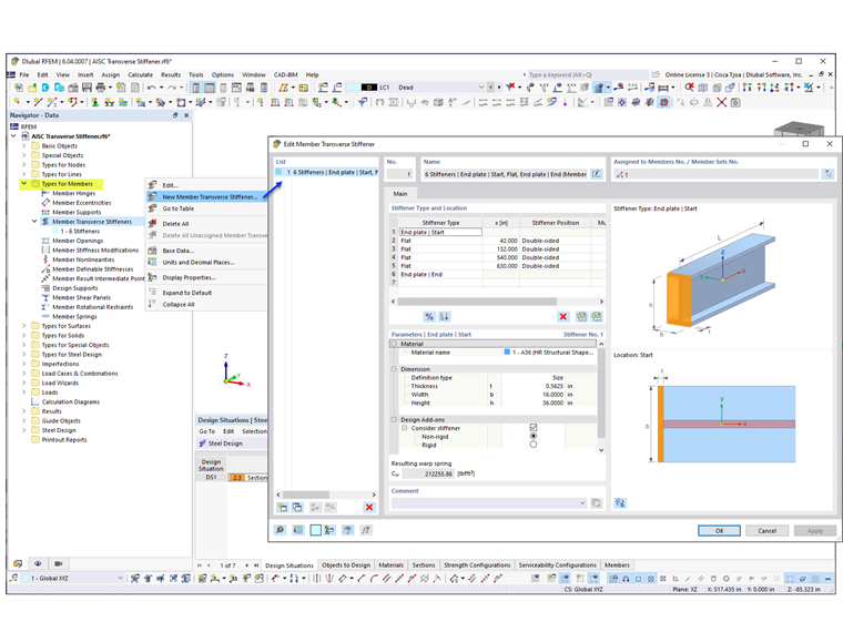
3) Добавить «Поперечные элементы жесткости стержня», указанные в списке в «Типы для стержней» в RFEM
В программе имеется несколько типов элементов жесткости. В нашем примере «торцевая пластина» используется в начале и на конце стержня. Для промежуточных элементов жесткости выбрано значение «плоский». Для каждого элемента жесткости задано положение, материал и размер.
Опция «учитывать элемент жёсткости» появляется с момента активации аддона Расчёт стальных конструкций. Данную функцию можно свободно включать и выключать для того, чтобы учесть в расчете влияние каждого отдельного элемента жесткости. Для «торцевой пластины» элемент жёсткости может быть задан «нежёстким» или «жёстким». «Нежёсткий» выбирается в случае, когда действие области растяжения не может быть учтено для торцевой панели.
Результирующая пружина депланации рассчитывается автоматически. Однако, она не учитывается в расчете без аддона Депланация при кручении (7 СтСв). При расчете с 6 степенями свободы поперечные элементы жёсткости не влияют на жёсткость.
4) Прочность на сдвиг в аддоне Расчёт стальных конструкций
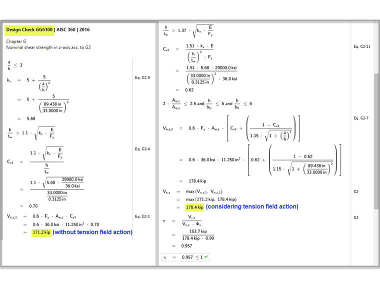
Как указано в разделе G2.2, можно применить большую номинальную прочность на сдвиг из раздела G2.1 (без действия области растяжения) и раздела G2.2 (с учетом действия области растяжения). Оба условия проверяются в аддоне Расчёт стальных конструкций в расчёте GG6100.
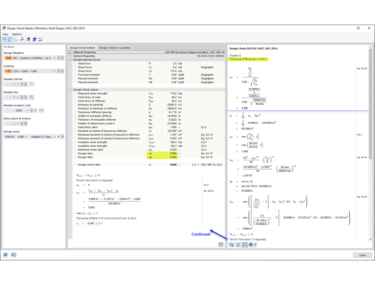
5) Требования к поперечному элементу жесткости по AISC, раздел G2.3 [1]
Кроме определения прочности стержня на сдвиг, расчёт GG6130 проверяет:
- Соотношение ширины и толщины элемента жёсткости (AISC уравнение G2-12)
- Момент инерции элемента жесткости (AISC уравнение G2-13)
Используя опцию «поперечные элементы жесткости стержня», вы можете учесть в RFEM усиленные стенки составных балок.