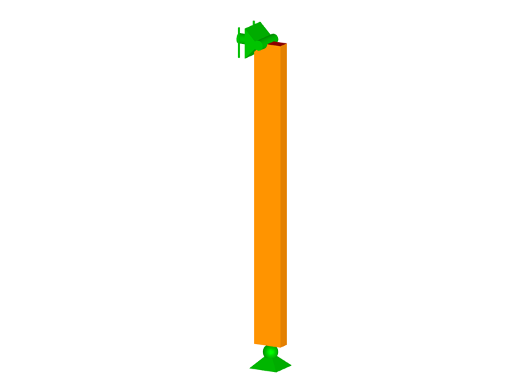
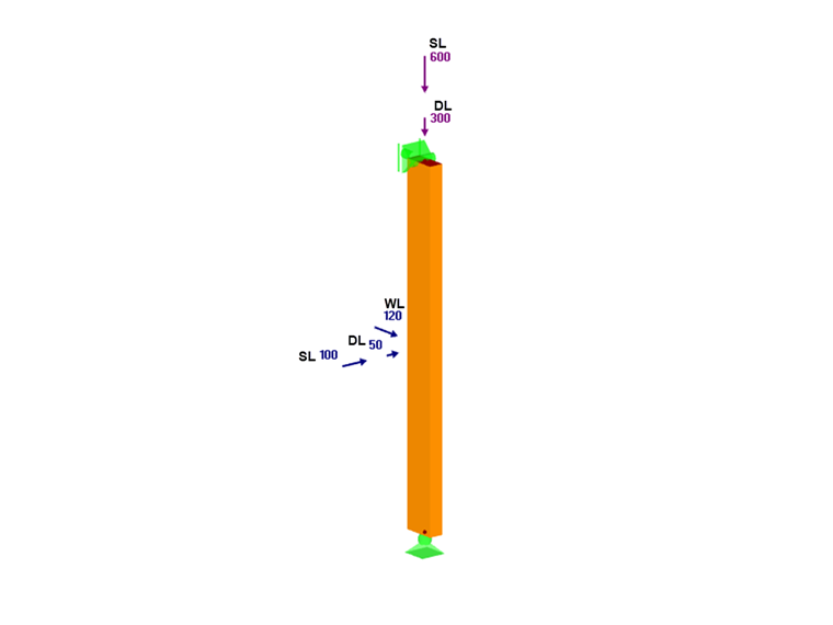
A barra é um Pinho do Sul nº 2, nominal 2x4, com 3 pés de comprimento e usado como barra de treliça. O apoio lateral é fornecido apenas nas extremidades da barra, e eles são considerados como articuladas. As cargas de peso próprio (DL), neve (SL) e vento (WL) são aplicadas no topo e no ponto médio do pilar-viga, conforme apresentado abaixo.
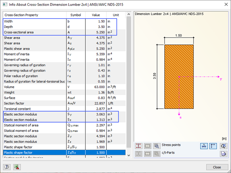
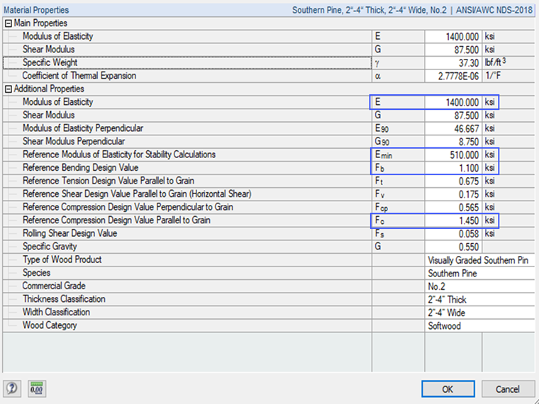
As propriedades da barra são apresentadas após selecionar a seção transversal e o material apropriados no programa.
Fatores de ajuste listados na Tabela 4.3.1 da NDS 2018 para o dimensionamento ASD
Os valores de referência de cálculo (Fb, Fc, e Emin) são multiplicados pelos fatores de ajuste aplicáveis para determinar os valores ajustados de cálculo. Para madeira serrada, estes fatores encontram-se na Tabela 4.3.1 [1]. Existem onze diferentes fatores de ajuste para o dimensionamento ASD. Muitos destes fatores são iguais a 1,0 no exemplo NDS [2]. No entanto, é apresentada abaixo uma breve descrição e como o RF-/TIMBER AWC tem em consideração cada fator.
Fatores calculados pelo programa
CL – Fator de estabilidade da viga
Depende da geometria e do apoio lateral da barra conforme descrito na Seção 3.3.3 [1]. Este fator é calculado automaticamente no RF-/TIMBER.
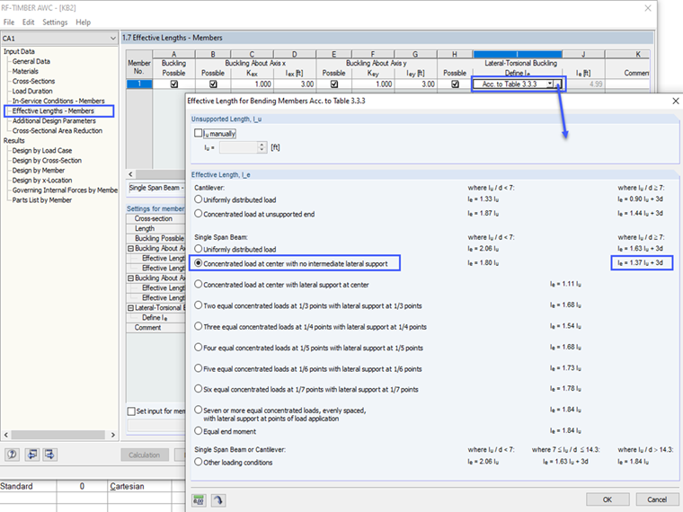
Nota: o comprimento efetivo, le, usado para calcular CL é definido pelo utilizador na seção "Comprimento Efetivo" do RF-/TIMBER AWC. Deve ser selecionada a opção "De acordo com a Tabela 3.3.3" com o caso de carga apropriado.
A imagem abaixo mostra o caso de carga aplicável para este exemplo.
CF – Fator de tamanho
Depende da profundidade e espessura da barra conforme especificado na Seção 4.3.6 [1]. Este fator é determinado automaticamente no RF-/TIMBER AWC.
Cfu – Fator de utilização plana
Considera a flexão do eixo fraco da barra conforme especificado na Seção 4.3.7 [1]. Este fator é calculado automaticamente no RF-/TIMBER AWC.
CP – Fator de estabilidade do pilar
Depende da geometria, condições de fixação das extremidades e apoio lateral da barra conforme descrito na Seção 3.7.1 [1]. Quando uma barra de compressão é totalmente apoiada ao longo de seu comprimento, CP = 1.0. Este fator é calculado automaticamente no RF-/TIMBER AWC para as duas as direções do eixo forte e fraco.
Fatores definidos pela introdução de dados do utilizador
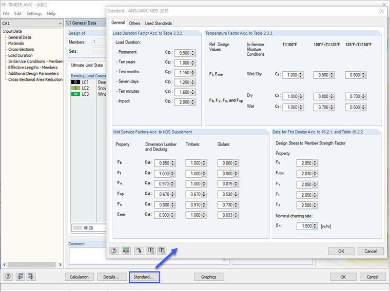
CD – Fator de duração da carga
Considera vários períodos de carga com base no caso de carga, tais como, peso próprio, neve e vento, com base na Seção 4.3.2 [1]. Selecionar "ASCE 7-16 NDS (Madeira)" como norma no RFEM ativa a opção de duração da carga na caixa de diálogo casos de carga. A configuração por defeito da classe de duração da carga (Permanente, Dez Anos, etc.) baseia-se na "Categoria de Ação" do caso de carga. Esta configuração pode ser ajustada pelo utilizador no RFEM ou RF-/TIMBER AWC. O valor selecionado pelo programa é baseado na Tabela 2.3.2 [1].
CM – Fator de serviço úmido
Considera as condições de serviço de umidade da barra conforme especificado na Seção 4.1.4 [1]. O utilizador pode selecionar "úmido" ou "seco" na seção 'Condições de Serviço' do RF-/TIMBER AWC.
Ct – Fator de temperatura
Considera a exposição a temperaturas elevadas de até 100 graus F, 100 a 125, e 125 a 150 conforme descrito na Seção 2.3.3 [1]. O utilizador pode selecionar entre as três faixas de temperatura na seção "Condições de Serviço" do RF-/TIMBER AWC. O valor selecionado pelo programa é baseado na Tabela 2.3.3 de [1].
Ci – Fator de incisão
Tem em consideração a perda da área devido às pequenas incisões feitas na barra para receber tratamento preservativo para prevenção de decadência conforme descrito na Seção 4.3.8 [1]. O utilizador pode selecionar "Não Incisado" ou "Incisado" na seção "Parâmetros de dimensionamento adicionais" do RF-/TIMBER AWC.
Cr – Fator de barra repetitiva
É utilizado quando múltiplas barras agem em conjunto para distribuir adequadamente uma carga entre si conforme descrito na Seção 4.3.9 [1]. Cr = 1.15 para barras que cumprem os critérios de estarem espaçados de perto e conectados por uma placa ou equivalente. O utilizador pode selecionar "Não Repetitivo" ou "Repetitivo" na seção "Parâmetros de dimensionamento adicionais" do RF-/TIMBER AWC.
Nota: Se necessário, os valores com base na norma dos fatores de ajuste de introduzidos pelo utilizador podem ser alterados na opção "Norma".
Fatores excluídos no programa
CT – Fator de rigidez da encurvadura
Tem em consideração a contribuição do revestimento de madeira prensada para a resistência à encurvadura dos banzos da treliça de compressão conforme especificado na Seção 4.4.2 [1]. Este fator é usado para aumentar Emin da barra. CT pode ser calculado manualmente conforme a Equação 4.4-1 [[#Refer [1]]] ou pode ser considerado de forma conservadora como 1.0.
Cb – Fator de área resistente
É utilizado para aumentar os valores de compressão de cálculo (Fcp) para cargas concentradas aplicadas perpendicularmente às fibras conforme especificado na Seção 3.10.4 [1]. Cb pode ser calculado manualmente conforme a equação 3.10-2 [1] ou conservadoramente considerado como 1.0.
Tensão real no pilar-viga
Neste exemplo, a combinação de carga foi simplificada para CO1: DL + SL + WL.
- Tensão de compressão das cargas de peso próprio e de neve, fc = 171 psi
- Tensão de flexão do eixo forte pela carga de vento, fbx = fb1 = 353 psi
- Tensão de flexão do eixo fraco pelas cargas de peso próprio e de neve, fby = fb2 = 1,029 psi
Determinação dos Valores de cálculo ajustados de acordo com Tabela 4.3.1 NDS 2018 Método ASD
- Valor de encurvadura crítica de cálculo para a barra de compressão no eixo forte, FcEx:
FcEx
Critical buckling design value for the compression member in the major axis, psi
Emin'
= Emin ⋅ CM ⋅ CT ⋅ Ci = 510,000 psi
le1
Effective length = 36.0 in
d1
Member depth = 3.5 in
- Valor de encurvadura crítica de cálculo para a barra de compressão no eixo fraco, FcEy:
FcEy
Critical buckling design value for the compression member in the minor axis, psi
Emin'
= Emin ⋅ CM ⋅ CT ⋅ Ci = 510,000 psi
le2
Effective length = 36.0 in
d2
Member thickness = 1.5 in
- Valor de cálculo de compressão ajustado paralelo à fibra, Fc':
Fc'
Adjusted compressive design value parallel to the grain, psi
Fc
Reference compressive design values parallel to the grain, psi
CD
Load duration factor
CM
Wet service factor
Ct
Temperature factor
CF
Size factor
Ci
Incising factor
CP
Column stability factor
- Valor de encurvadura crítica de cálculo para barra de flexão, FbE:
FbE
Critical buckling design value for the bending member, psi
Emin'
= Emin ⋅ CM ⋅ CT ⋅ Ci = 510,000 psi
RB
Slenderness ratio = 9.65 < 50 (NDS Equation 3.3-5)
- Valor de cálculo ajustado de flexão do eixo forte, Fbx':
Fbx'
Adjusted major axis bending design value, psi
Fb
Reference bending design value, psi
CD
Load duration factor
CM
Wet service factor
CL
Beam stability factor
Ct
Temperature factor
CF
Size factor
Ci
Incising factor
Cr
Repetitive member factor
- Valor de cálculo ajustado de flexão do eixo fraco, Fby':
Fby'
Adjusted minor axis bending design value, psi
Fb
Reference bending design value, psi
CD
Load duration factor
CM
Wet service factor
CL
Beam stability factor
Ct
Temperature factor
Cfu
Flat use factor
CF
Size factor
Ci
Incising factor
Cr
Repetitive member factor
- Relação da combinada de flexão biaxial e compressão axial de cálculo
Inserindo as tensões reais e os valores limites de cálculo apresentados acima na equação NDS 3.9-3 [1], a relação final do dimensionamento é apresentada abaixo.
|
fc |
Compression stress due to the dead and snow load |
|
Fc' |
Adjusted compressive design value parallel to the grain |
|
fbx |
Major-axis bending stress due to the wind load |
|
Fbx' |
Adjusted major axis bending design value |
|
FcEx |
Critical buckling design value for the compression member in the major axis |
|
fby |
Minor-axis bending stress due to the dead and snow load |
|
Fby' |
Adjusted minor axis bending design value |
|
FcEy |
Critical buckling design value for the compression member in the minor axis |
|
FbE |
Critical buckling design value for the bending member |
E a equação NDS 3.9-4 [1],
|
fc |
Compression stress due to the dead and snow load |
|
FcEy |
Critical buckling design value for the compression member in the minor axis |
|
fbx |
Major-axis bending stress due to the wind load |
|
FbE |
Critical buckling design value for the bending member |
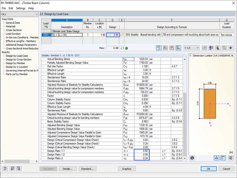
Resultado no RF-/TIMBER AWC
O utilizador pode comparar cada fator de ajuste e valor de cálculo ajustado do método de cálculo analítico à mão com o resumo dos resultados no RF-/TIMBER AWC. Como apresentado, os resultados são idênticos. A relação de dimensionamento final controladora = 0,98 é baseada no método de cálculo linear geométrico (1º grau). Tenha em consideração que a configuração definida por defeito no RFEM para a combinação de carga está definida para a análise de segunda ordem. Isso resultará em uma relação de dimensionamento ligeiramente maior = 1,03. O utilizador tem a opção de escolher qual método listado nos "Parâmetros de Cálculo" é o melhor para a estrutura.