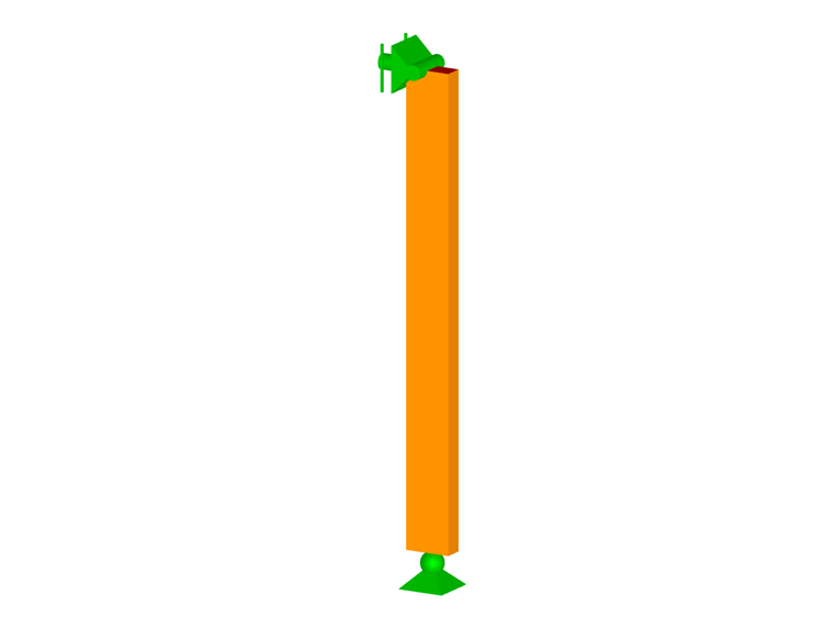
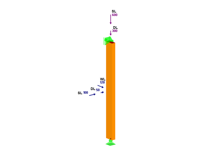
The member is a No. 2 Southern Pine, 2x4 nominal, 3 feet long and used as a truss member. Lateral support is provided only at the member ends, and they are considered pinned. The dead (DL), snow (SL), and wind (WL) loads are applied at the top and midpoint of the beam-column, as shown below.
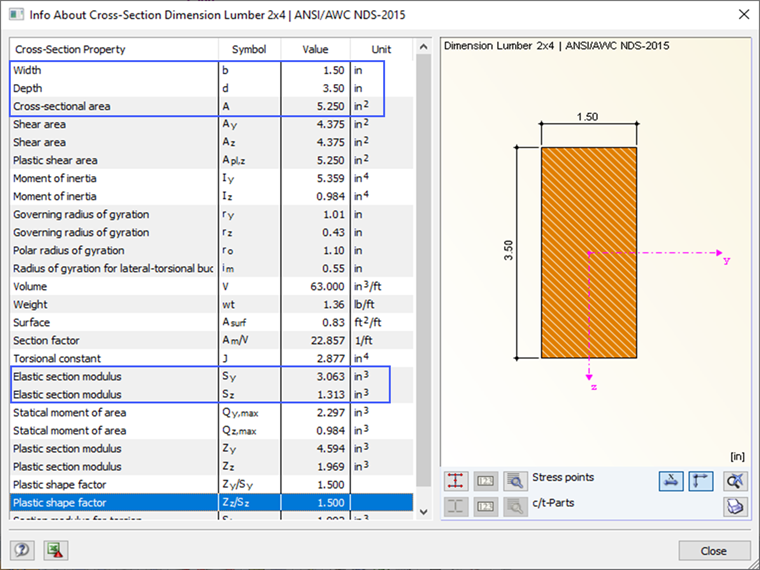
The member properties are shown after selecting the appropriate cross-section and material in the program.
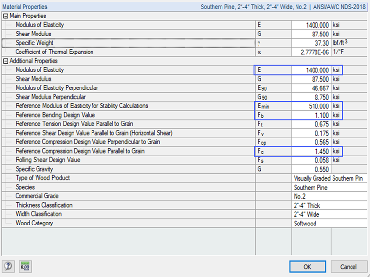
Adjustment Factors Listed in Table 4.3.1 of NDS 2018 for ASD Design
The reference design values (Fb, Fc, and Emin) are multiplied by the applicable adjustment factors to determine the adjusted design values. For sawn lumber, these factors are found in Table 4.3.1 [1]. There are eleven different adjustment factors for the ASD design. Many of these factors are equal to 1.0 in the NDS example [2]. However, a brief description and how RF-/TIMBER AWC accounts for each factor are given below.
Factors Calculated by Program
CL – Beam Stability Factor
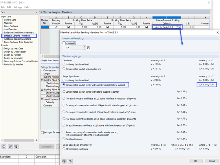
It depends on the geometry and lateral support of the member as described in Section 3.3.3 [1]. This factor is automatically calculated in RF-/TIMBER.
Note: the effective length, le, used to calculate CL is defined by the user in the "Effective Length" section of RF-/TIMBER AWC. The "Acc. to Table 3.3.3" option with the appropriate loading case must be selected.
The image below shows the applicable loading case for this example.
CF – Size Factor
It depends on the depth and thickness of the member as specified in Section 4.3.6 [1]. This factor is automatically determined in RF-/TIMBER AWC.
Cfu – Flat Use Factor
It accounts for weak axis bending of the member as specified in Section 4.3.7 [1]. This factor is automatically calculated in RF-/TIMBER AWC.
CP – Column Stability Factor
It depends on the geometry, end fixity conditions, and lateral support of the member as described in Section 3.7.1 [1]. When a compression member is fully supported throughout its length, CP = 1.0. This factor is automatically calculated in RF-/TIMBER AWC for both strong and weak axis directions.
Factors Defined by User Input
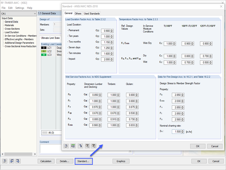
CD – Load Duration Factor
It accounts for various loading periods based on the load case, such as dead, snow, and wind, based on Section 4.3.2 [1]. Selecting "ASCE 7-16 NDS (Wood)" as the standard in RFEM activates the load duration option in the Load Cases dialog box. The load duration class (Permanent, Ten Years, and so on) default setting is based on the "Action Category" of the load case. This setting can be adjusted by the user in RFEM or RF-/TIMBER AWC. The value selected by the program is based on Table 2.3.2 [1].
CM – Wet Service Factor
It accounts for the moisture service conditions of the member as specified in Section 4.1.4 [1]. The user can select "wet" or "dry" in the 'In-Service Conditions' section of RF-/TIMBER AWC.
Ct – Temperature Factor
It accounts for exposure to elevated temperatures of up to 100 degrees F, 100 to 125, and 125 to 150 as described in Section 2.3.3 [1]. The user can select between the three temperature ranges in the "In-Service Conditions" section of RF-/TIMBER AWC. The value selected by the program is based on Table 2.3.3 of [1].
Ci – Incising Factor
It accounts for the loss of the area from the small incisions made in the member to receive preservative treatment for decay prevention as described in Section 4.3.8 [1]. The user can select "Not Incised" or "Incised" in the "Additional Design Parameters" section of RF-/TIMBER AWC.
Cr – Repetitive Member Factor
It is used when multiple members act compositely to properly distribute a load amongst themselves as described in Section 4.3.9 [1]. Cr = 1.15 for members that meet the criteria of being closely spaced and connected by a sheathing or equivalent. The user can select "Not Repetitive" or "Repetitive" in the "Additional Design Parameters" section of RF-/TIMBER AWC.
Note: If necessary, code-based values of the user input adjustment factors can be changed in the "Standard" option.
Factors Excluded in Program
CT – Buckling Stiffness Factor
It accounts for the contribution of plywood sheathing to the buckling resistance of compression truss chords as specified in Section 4.4.2 [1]. This factor is used to increase Emin of the member. CT can be manually calculated as per Equation 4.4-1 [[#Refer [1]]] or conservatively taken as 1.0.
Cb – Bearing Area Factor
It is used to increase the compression design values (Fcp) for concentrated loads applied perpendicular to the grain as specified in Section 3.10.4 [1]. Cb can be manually calculated per equation 3.10-2 [1] or conservatively taken as 1.0.
Actual Stress in Beam-Column
In this example, the load combination has been simplified to CO1: DL + SL + WL.
- Compression stress from dead and snow loads, fc = 171 psi
- Strong-axis bending stress from wind load, fbx = fb1 = 353 psi
- Weak-axis bending stress from dead and snow loads, fby = fb2 = 1,029 psi
Determination of Adjusted Design Values as per NDS 2018 Table 4.3.1 ASD Method
- Critical Buckling Design Value for Compression Member in Strong Axis, FcEx:
FcEx
Critical buckling design value for the compression member in the major axis, psi
Emin'
= Emin ⋅ CM ⋅ CT ⋅ Ci = 510,000 psi
le1
Effective length = 36.0 in
d1
Member depth = 3.5 in
- Critical Buckling Design Value for Compression Member in Weak Axis, FcEy:
FcEy
Critical buckling design value for the compression member in the minor axis, psi
Emin'
= Emin ⋅ CM ⋅ CT ⋅ Ci = 510,000 psi
le2
Effective length = 36.0 in
d2
Member thickness = 1.5 in
- Adjusted Compressive Design Value Parallel to Grain, Fc':
Fc'
Adjusted compressive design value parallel to the grain, psi
Fc
Reference compressive design values parallel to the grain, psi
CD
Load duration factor
CM
Wet service factor
Ct
Temperature factor
CF
Size factor
Ci
Incising factor
CP
Column stability factor
- Critical Buckling Design Value for Bending Member, FbE:
FbE
Critical buckling design value for the bending member, psi
Emin'
= Emin ⋅ CM ⋅ CT ⋅ Ci = 510,000 psi
RB
Slenderness ratio = 9.65 < 50 (NDS Equation 3.3-5)
- Adjusted Strong Axis Bending Design Value, Fbx':
Fbx'
Adjusted major axis bending design value, psi
Fb
Reference bending design value, psi
CD
Load duration factor
CM
Wet service factor
CL
Beam stability factor
Ct
Temperature factor
CF
Size factor
Ci
Incising factor
Cr
Repetitive member factor
- Adjusted Weak Axis Bending Design Value, Fby':
Fby'
Adjusted minor axis bending design value, psi
Fb
Reference bending design value, psi
CD
Load duration factor
CM
Wet service factor
CL
Beam stability factor
Ct
Temperature factor
Cfu
Flat use factor
CF
Size factor
Ci
Incising factor
Cr
Repetitive member factor
- Combined Biaxial Bending and Axial Compression Design Ratio
Inserting the actual stresses and limiting design values presented above into NDS equation 3.9-3 [1], the final design ratio is shown below.
|
fc |
Compression stress due to the dead and snow load |
|
Fc' |
Adjusted compressive design value parallel to the grain |
|
fbx |
Major-axis bending stress due to the wind load |
|
Fbx' |
Adjusted major axis bending design value |
|
FcEx |
Critical buckling design value for the compression member in the major axis |
|
fby |
Minor-axis bending stress due to the dead and snow load |
|
Fby' |
Adjusted minor axis bending design value |
|
FcEy |
Critical buckling design value for the compression member in the minor axis |
|
FbE |
Critical buckling design value for the bending member |
And NDS equation 3.9-4 [1],
|
fc |
Compression stress due to the dead and snow load |
|
FcEy |
Critical buckling design value for the compression member in the minor axis |
|
fbx |
Major-axis bending stress due to the wind load |
|
FbE |
Critical buckling design value for the bending member |
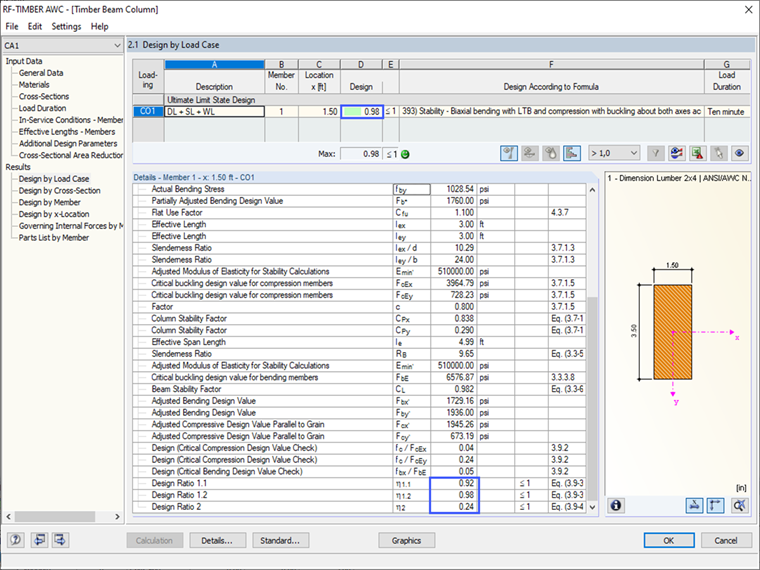
Result in RF-/TIMBER AWC
The user can compare each adjustment factor and adjusted design value from the analytical hand calculation method to the result summary in RF-/TIMBER AWC. As shown, the results are identical. The controlling final design ratio = 0.98 is based on the geometrically linear analysis (1st degree) calculation method. Keep in mind that the default setting in RFEM for the load combination is set to the second-order analysis. This will result in a slightly larger design ratio = 1.03. The user has the option to choose which method listed in the "Calculation Parameters" is best for the structure.