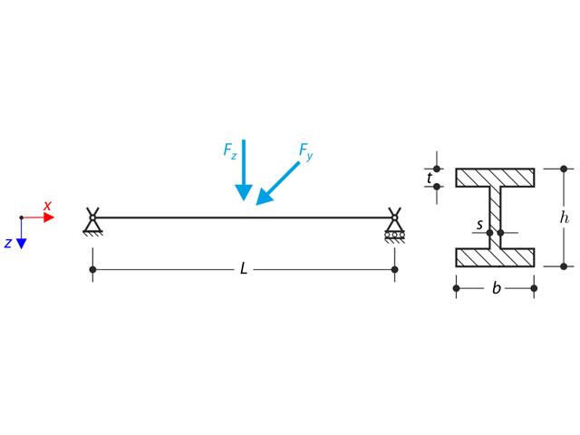
Une structure faite de profilé en I est intégrée dans les appuis des fourches. The axial rotation is restricted on both ends while warping is enabled. The structure is loaded by two transverse forces in the middle. The verification example is based on the example introduced by Gensichen and Lumpe.
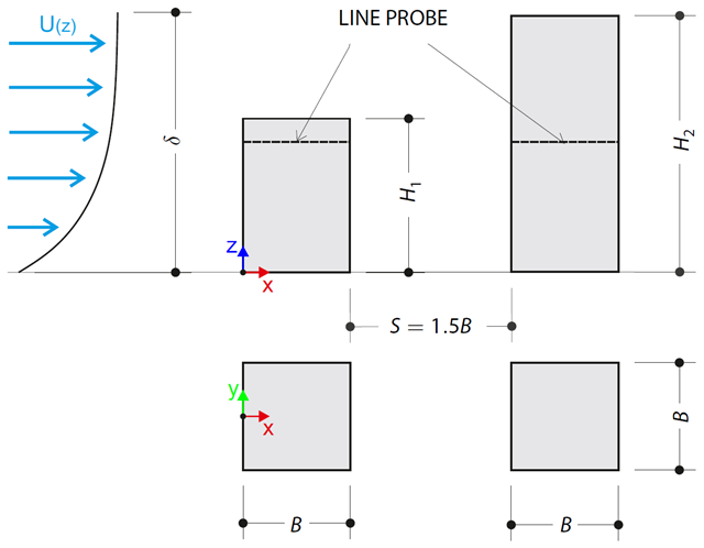
L'exemple de vérification décrit les charges de pression sur les voiles des bâtiments disposés en parallèle au niveau du sol. The buildings are simplified to rectangular objects and scaled down while maintaining the elevation ratios. The pressure distribution on the walls of the model of a medium-high building was conducted by an experiment. The chosen results (pressure coefficient Cp) are compared with the measured values.
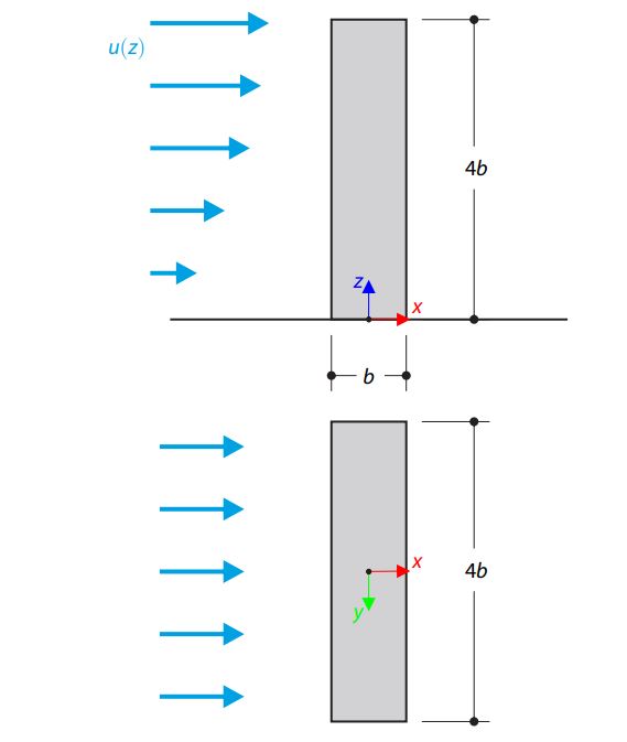
L'exemple de vérification décrit le flux stationnaire autour d'un bâtiment isolé (modèle à l'échelle) à l'aide d'un exemple de l'AIJ (Architectural Institute of Japan). The chosen results (velocity magnitude) are compared with the measured values.
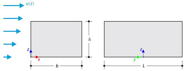
The verification example compares wind load calculation on a building with a flat roof using the standard EN 1991-1-4 and using CFD simulation in RWIND Simulation. Le bâtiment est défini d'après le croquis et le profil de vitesse d'afflux est calculé selon la norme EN 1991-1-4.
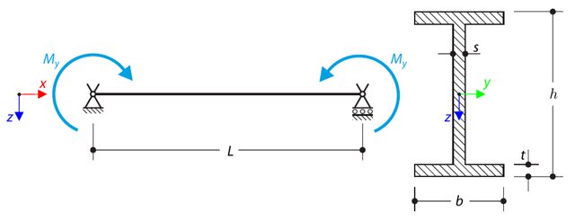
Une poutre sur appuis simples est chargée en flexion seule. Determine the critical load and corresponding load factor due to lateral buckling.
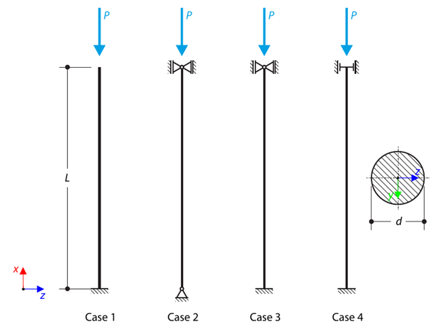
Une bielle de section circulaire est supportée selon quatre cas de base de flambement selon Euler et est soumise à une force de pression. Determine the critical load.
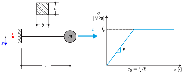
Cet exemple de vérification est basé sur l'exemple de vérification 0122. A single-mass system without damping is subjected to an axial loading force. An ideal elastic-plastic material with characteristics is assumed. Determine the time course of the end-point deflection, velocity, and acceleration.
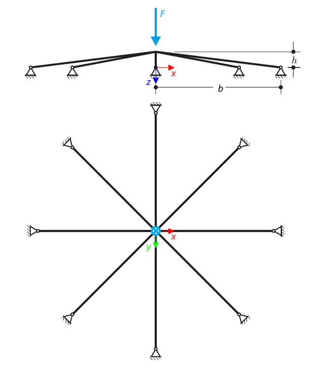
A symmetrical shallow structure is made of eight equal truss members, which are embedded into hinge supports. The structure is loaded by a concentrated force and alternatively by imposed nodal deformation over the critical limit point when the snap-through occurs. Imposed nodal deformation is used in RFEM 5 and RSTAB 8 to obtain the full equilibrium path of the snap-through. Le poids propre est négligé dans cet exemple. Determine the relationship between the actual loading force and the deflection, considering large deformation analysis. Evaluate the load factor at the given deflections.
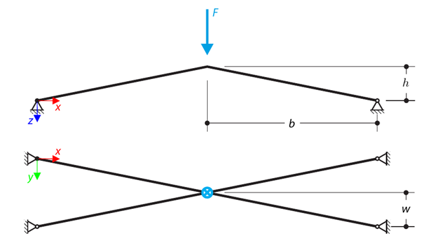
A structure is made of four truss members, which are embedded into hinge supports. The structure is loaded by a concentrated force and alternatively by imposed nodal deformation over the critical limit point, when snap-through occurs. Imposed nodal deformation is used in RFEM 5 and RSTAB 8 to obtain the full equilibrium path of the snap-through. Le poids propre est négligé dans cet exemple. Determine the relationship between the actual loading force and the deflection, considering large deformation analysis. Evaluate the load factor at given deflections.
Considérons la travée de barre ASTM A992 W 18×50 ainsi que les poids propre et les charges d'exploitation représentés sur la Figure 1. The member is limited to a maximum nominal depth of 18 inches. The live load deflection is limited to L/360. The beam is simply supported and continuously braced. Verify the available flexural strength of the selected beam, based on LRFD and ASD.