


ACI 318-19 Secc. 8.4.1.5 y 8.4.1.6 recomienda el uso de bandas de columnas y bandas intermedias para el diseño de losas bidireccionales. Las bandas de columnas incluyen un ancho de 0.25lmin a cada lado de la línea central de la columna. Una banda intermedia se coloca entre dos bandas de columnas. De manera similar, la CSA A23.3:19 también especifica anchos de bandas de columnas como 0.25lmin, mientras que la banda intermedia es el área delimitada por dos bandas de columnas.
Enfoque de Superficies RF-CONCRETE
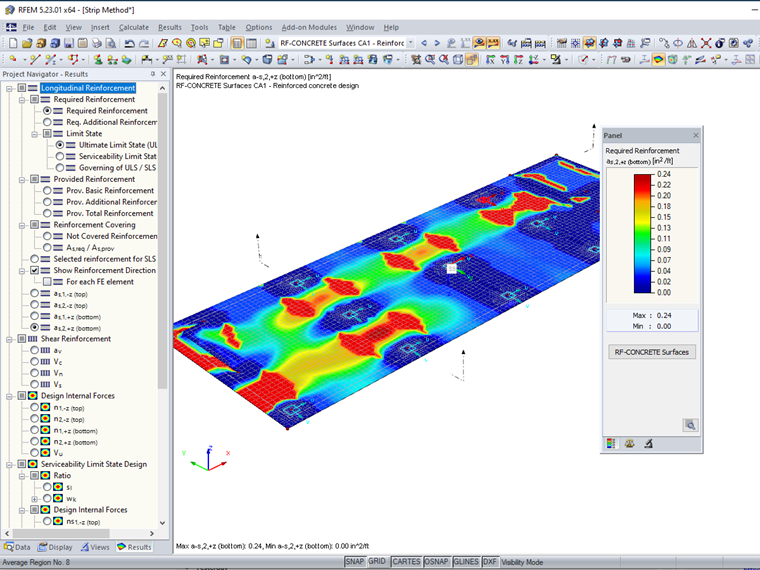
El enfoque de diseño predeterminado en el módulo de Superficies RF-CONCRETE es el diseño de losas bidireccionales. El programa FEA principal RFEM ejecuta un análisis completo por elementos finitos para determinar las fuerzas internas básicas como mx y my para todos los elementos de superficie 2D dentro del modelo. Las fuerzas internas básicas definidas por los ejes locales de las superficies (x, y, y z) se transforman además en fuerzas internas principales como m1 y m2 relacionadas con los ejes principales 1 y 2. Se puede encontrar más información sobre esta transformación en el Manual en línea de RFEM:
Superficies RF-CONCRETE calcula además los momentos de diseño finales para ambos lados superior e inferior de la placa orientados a lo largo de las direcciones de refuerzo definidas. Consulte el Manual en línea de Superficies RF-CONCRETE 2.4.1 Design Internal Forces para obtener información detallada sobre este flujo de cálculo:
Los momentos de diseño finales se consideran en cada punto de malla FE como una tira de ancho de 1 ft (o 1 m) en la dirección del refuerzo longitudinal. El refuerzo a lo largo de esta tira se determina sobre la base de este momento de diseño junto con consideraciones del estándar de diseño, como mínimos de refuerzo. Las unidades para el refuerzo dado son [área de refuerzo / ancho], que es en²/ft (o cm²/m). El refuerzo requerido en cada punto de malla FE se proporciona en representación gráfica usando líneas de contorno coloreadas.
Los ingenieros pueden estar interesados en considerar un ancho de diseño mayor en lugar del valor predeterminado de 1 ft (o 1 m) como lo permite ACI 318-19 o CSA A23.3:19 para un enfoque más simplificado.
Tiras de Diseño con Vigas de Resultados en Miembros RF-CONCRETE
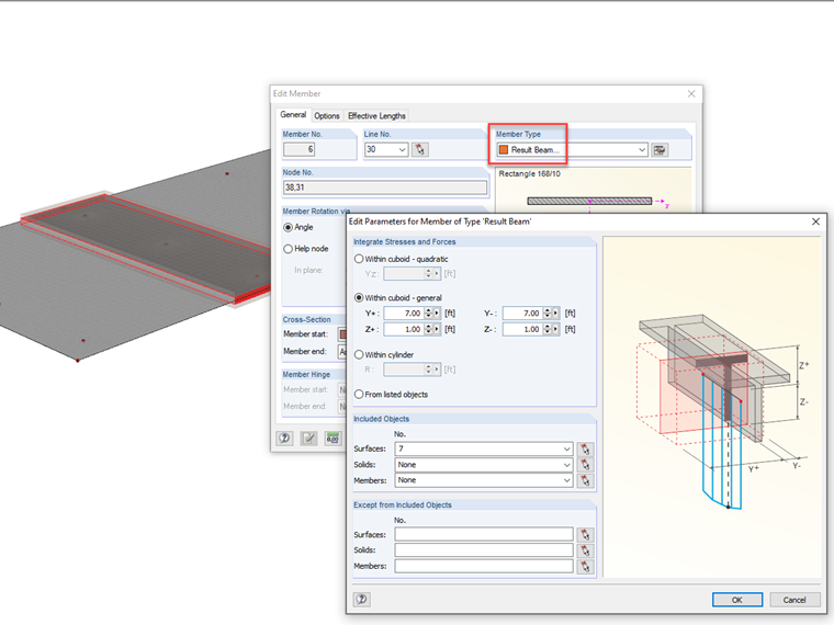
Las vigas de resultados tienen la capacidad de sumar todas las fuerzas internas de un elemento de losa sobre una longitud y ancho elegidos. Las vigas de resultados no contribuyen a la rigidez de la estructura ni influyen en la distribución de la carga. Más bien, se pueden usar como una herramienta de evaluación de resultados. Vea el Manual de Ayuda en línea de RFEM 4.17 Miembros para una explicación detallada de este tipo de miembro:
Se puede dibujar una viga de resultados directamente sobre el elemento de losa. El tipo de sección transversal y material puede ser cualquier selección arbitraria. El tipo de miembro debe configurarse como "viga de resultados". La opción "Dentro del cuboide – general" debe seleccionarse adicionalmente con el ancho Y configurado al ancho total de la tira de diseño deseada y la altura Z configurada para abarcar el grosor de la superficie. La(s) superficie(s) que la tira de diseño abarca deben enumerarse en los "Objetos Incluidos".
Vea el seminario web de RFEM 2: Modelado Avanzado en el minuto 38:14 para ver un ejemplo similar de una viga de resultados aplicada a un elemento de losa.
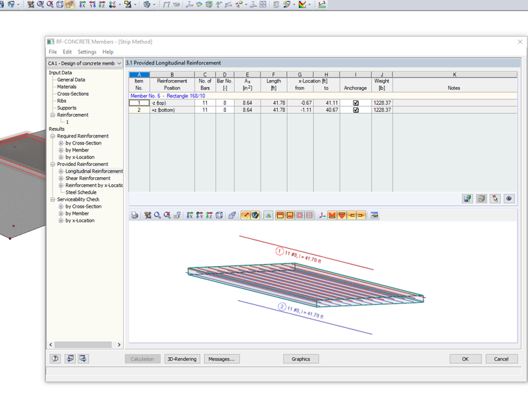
Las vigas de resultados pueden diseñarse además en el módulo Miembros RF-CONCRETE como un elemento de viga típico.
El refuerzo longitudinal se proporcionará de acuerdo con los estándares ACI 318 o CSA A23.3 basados en el momento de flexión promedio a lo largo de la longitud de la viga.
Se pueden crear múltiples vigas de resultados en ambas direcciones longitudinales y diseñarse en el Módulo RF-CONCRETE para aplicar el método de tira de diseño unidireccional para elementos de losa. Vea la Superficie 7 y el Miembro 6 en el modelo de descarga al final del artículo para este ejemplo de viga de resultados.
Tiras de Diseño con Regiones Promedio en Superficies RF-CONCRETE
La alternativa a las vigas de resultados es aplicar regiones promedio sobre el ancho de tira de diseño especificado. Las regiones promedio promedian las fuerzas internas sobre el área designada en un elemento de superficie que se puede considerar además para el diseño en Superficies RF-CONCRETE. Lea más sobre regiones promedio en el Manual de Ayuda en línea de RFEM 9.7.3 Average Regions:
Las regiones promedio son beneficiosas para situaciones de singularidad. Consulte artículos adicionales sobre "regiones promedio" en la Base de Conocimientos:
También pueden considerarse en el módulo Superficies RF-CONCRETE para suavizar picos altos en fuerzas internas y tensiones que no ocurrirían en situaciones reales debido a una mejor distribución de carga que un software FEA no puede capturar por defecto. Vea el seminario web de Diseño de Concreto CSA A23.3:19 en RFEM en el minuto 56:10 para ver un ejemplo de regiones promedio y singularidades para el diseño de concreto reforzado.
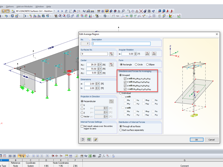
Además, la Superficie 9 en el modelo de descarga aplica el uso de regiones promedio solo alrededor de las intersecciones de columna a losa para evitar altos requisitos de refuerzo máximo. Las fuerzas internas se promedian en todas las direcciones sobre un área de 2 ft ⋅ 2 ft.
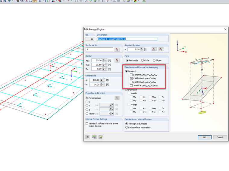
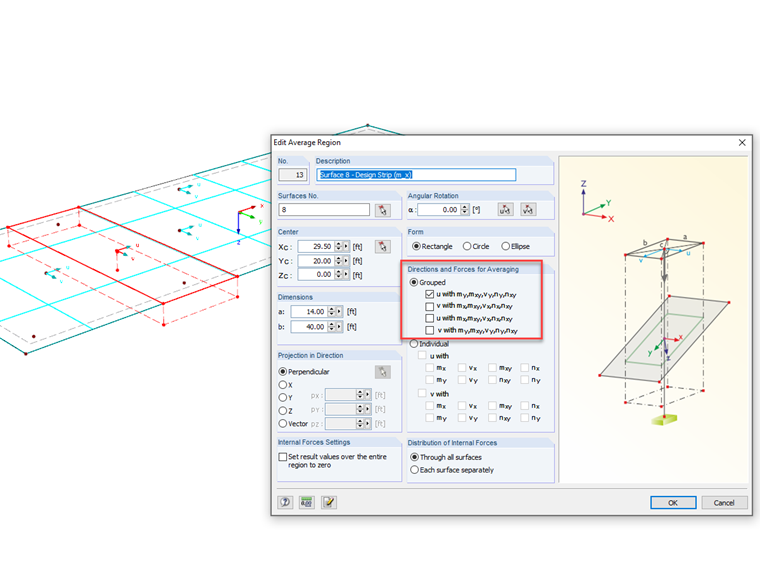
Las regiones promedio también pueden usarse para replicar tiras de diseño para consideraciones de refuerzo. La Superficie 8 es idéntica a la Superficie 9 en el modelo de descarga. Sin embargo, se aplican tiras de diseño a lo largo de todo el ancho y largo de la losa en ambas direcciones X e Y en lugar de solo en ubicaciones de singularidad. El ancho de la tira de diseño lo establecería el usuario y probablemente consideraría las recomendaciones de ACI 318 y CSA A23.3.
También es extremadamente importante dar especial consideración a los detalles de "Direcciones y Fuerzas para Promediar" en el cuadro de diálogo Editar Región Promedio. Las tiras de diseño están destinadas para un diseño unidireccional. Por lo tanto, las regiones promedio solo deberían considerar promediar las fuerzas internas en la dirección correspondiente. Esto se puede establecer alineando el eje local de la región promedio con el eje local perpendicular de la superficie (por ejemplo, el eje u de la región promedio con el eje y de la superficie). Estas configuraciones dependerán de la orientación de los elementos en el modelo usado. Las fuerzas internas relevantes se promediarán a través del ancho de la tira de diseño.
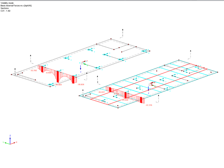
La presentación de las fuerzas internas básicas de las superficies, como los momentos de flexión del eje x (mx), muestra una diferencia significativa para los valores predeterminados a lo largo de un corte seccional que incluye fuerzas máximas altas (Superficie 9) frente a valores de corte seccional promediados sobre un ancho de región promedio (Superficie 8).
El diseño de refuerzo en Superficies RF-CONCRETE puede considerar las regiones promedio seleccionando esta opción en los ajustes de "Detalles" dentro del módulo. El diseño luego considerará las regiones promedio implementadas en la superficie. Con esto dicho, aunque las regiones promedio afectarán directamente las fuerzas internas básicas a lo largo del eje x e y de la superficie, estos no son los valores utilizados para el diseño final. Más bien, se utilizan las fuerzas internas de diseño final que se derivaron de momentos de flexión máximos y mínimos no necesariamente orientados a lo largo del eje x e y. No es posible eliminar el diseño bidireccional en el módulo. Las regiones promedio utilizadas como tiras de diseño proporcionarán mejor uniformidad al diseño de refuerzo, pero no son un diseño unidireccional estricto.
Conclusión
Superficies RF-CONCRETE es un módulo de diseño de losas con refuerzo bidireccional por defecto. El refuerzo requerido del análisis se proporcionará tanto en salida numérica como gráfica en cada punto de malla de elemento finito basado en las fuerzas internas de diseño finales calculadas dentro del módulo. La forma óptima de considerar el método de tira de diseño para un diseño auténtico de concreto reforzado unidireccional sobre un ancho definido por el usuario es con el uso de vigas de resultados y el módulo complementario Miembros RF-CONCRETE. La alternativa es aplicar regiones promedio dentro del modelo de RFEM y activar esta consideración dentro de Superficies RF-CONCRETE. La última opción mejorará el promedio de fuerzas internas sobre el ancho de una tira de diseño, pero el diseño bidireccional aún se considerará en el proceso de diseño de refuerzo.