


ACI 318-19 Sec. 8.4.1.5 and 8.4.1.6 recommends using column and middle strips for two-way slab design. Column strips include a width of 0.25lmin on either side of the column centerline. A middle strip is placed between two column strips. Similarly, the CSA A23.3:19 also specifies column strip widths as 0.25lmin while the middle strip is the area bounded by two column strips.
RF-CONCRETE Surfaces Approach
The default design approach in the RF-CONCRETE Surface module is two-way slab design. The main FEA program RFEM runs a full finite element analysis to determine the basic internal forces such as mx and my for all 2D surface elements within the model. The basic internal forces defined by the surfaces' local axes (x, y, and z) are further transformed into principal internal forces such as m1 and m2 related to the principal axes 1 and 2. More information on this transformation can be found in the RFEM Online Manual:
8.16 Surfaces – Principal Internal Forces
RF-CONCRETE Surfaces further calculates the final design moments for both the top and bottom sides of the plate oriented along the defined reinforcement directions. See the RF-CONCRETE Surfaces Online Manual 2.4.1 Design Internal Forces for detailed information on this calculation workflow:
The final design moments are considered at every FE mesh point as a 1 ft (or 1 m) width strip in the direction of the longitudinal reinforcement. The reinforcement along this strip is determined on the basis of this design moment along with considerations from the design standard, such as reinforcement minimums. The units for the reinforcement given are [reinforcement area / width], which is in²/ft (or cm²/m). Required reinforcement at every FE mesh point is provided in graphical representation using colored contour lines.
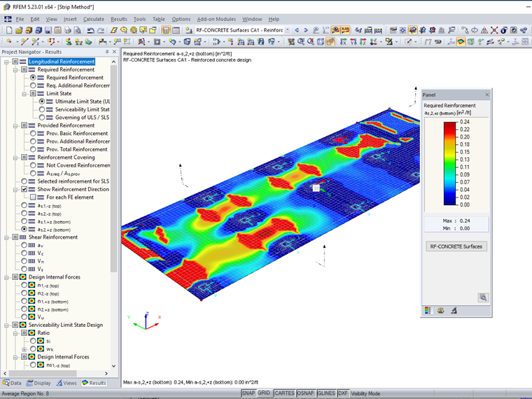
Engineers may be interested in considering a larger design width rather than the default 1 ft (or 1 m) such as what the ACI 318-19 or the CSA A23.3:19 allows for a more simplified approach.
Design Strips with Result Beams in RF-CONCRETE Members
Result beams have the capability to sum all internal forces of a slab element over a chosen length and width. Result beams do not contribute to the stiffness of the structure or influence the load distribution. Rather, they can be used as a result evaluation tool. View the RFEM Online Help Manual 4.17 Members for a detailed explanation of this member type:
Online Manual RFEM 5 | 4 Model Data | 4.17 Members
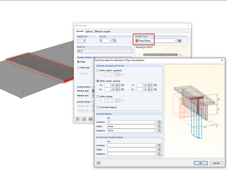
A result beam can be drawn directly over the slab element. The cross-section type and material can be any arbitrary selection. The member type must be set to "result beam". The "Within cuboid – general" option should further be selected with the width Y set to the total width of the desired design strip and the height Z set to encompass the surface thickness. The surface(s) that the design strip spans over should be listed in the "Included Objects".
View RFEM Webinar 2: Advanced Modeling at time 38:14 to see a similar example of a result beam applied over a slab element.
Result beams can further be designed in the RF-CONCRETE Members module like a typical beam element.
Longitudinal reinforcement will be provided according to the ACI 318 or CSA A23.3 standards based on the average bending moment along the beam length.
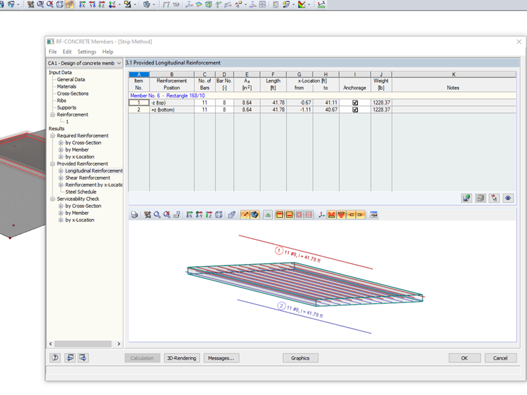
Multiple results beams can be created in both longitudinal directions and designed in the RF-CONCRETE Module to apply the one-way design strip method for slab elements. See Surface 7 and Member 6 in the download model at the end of the article for this result beam example.
Design Strips with Average Regions in RF-CONCRETE Surfaces
The alternative to results beams is to apply average regions over the specified design strip width. Average regions average the internal forces over the designated area on a surface element which can further be considered for design in RF-CONCRETE Surfaces. Read more about average regions in the RFEM Online Help Manual 9.7.3 Average Regions:
Average regions are beneficial for singularity situations. See additional articles on "average regions" in the Knowledge Base:
They can also be considered in the RF-CONCRETE Surfaces module to smooth out high peaks in internal forces and stresses that would not occur in real-life situations due to better load distribution that an FEA software cannot capture by default. See the CSA A23.3:19 Concrete Design in RFEM webinar at time 56:10 to view an example of average regions and singularities for reinforced concrete design.
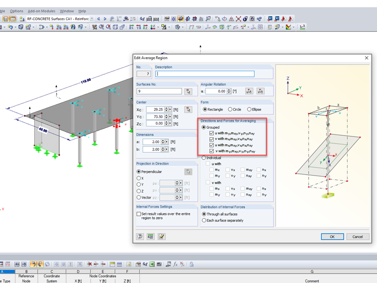
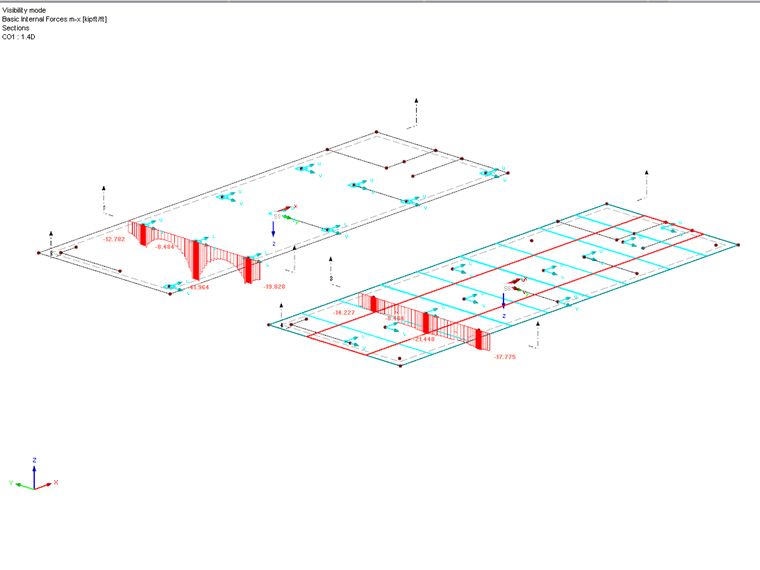
Additionally, Surface 9 in the download model applies the use of average regions only around column to slab intersections to avoid high peak reinforcement requirements. Internal forces are averaged in all directions over a 2 ft ⋅ 2 ft area.
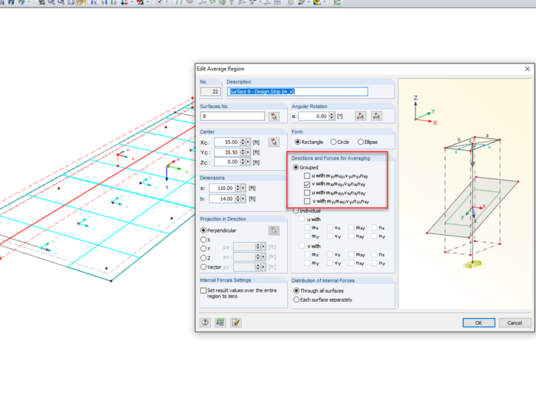
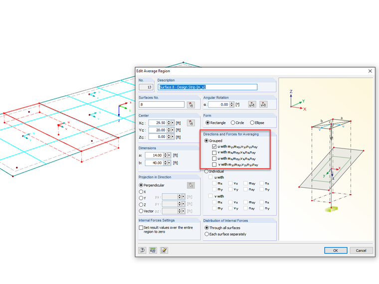
Average regions can also be used to replicate design strips for reinforcement considerations. Surface 8 is identical to Surface 9 in the download model. However, design strips are applied along the entire slab width and length in both the X and Y directions rather than at singularity locations only. The width of the design strip would be set by the user and likely consider the recommendations from ACI 318 and CSA A23.3.
It is also extremely important to give special consideration to the "Directions and Forces for Averaging" details in the Edit Average Region Dialog box. Design strips are meant for one-way design. Therefore, the average regions should only consider averaging out internal forces in the corresponding direction. This can be set by aligning the local axis of the average region to the perpendicular local axis of the surface (for example, average region's u-axis with surface's y-axis). These settings will depend on the orientation of the elements in the used model. The relevant internal forces will be averaged across the width of the design strip.
The display of the surfaces' basic internal forces such as the x-axis bending moments (mx) shows a significant difference for default values along a section cut including high peak forces (Surface 9) versus section cut values averaged out over an average region width (Surface 8).
The reinforcement design in RF-CONCRETE Surfaces can consider the average regions by selecting this option under the "Details" settings within the module. The design will then consider the average regions implemented on the surface. With this said, although average regions will directly affect the basic internal forces along the surface's x- and y-axis, these are not the values used for the final design. Rather, the final design internal forces are used which were derived from maximum and minimum bending moments not necessarily oriented along the x- and y-axis. It is not possible to eliminate two-way design in the module. The average regions used as design strips will provide better uniformity to the reinforcement design, but are not strict one-way design.
Conclusion
RF-CONCRETE Surfaces is a two-way reinforcing slab design module by default. Required reinforcement from the analysis will be provided in both the numerical and graphical output at each finite element mesh point based on the final design internal forces calculated within the module. The optimal way to consider the design strip method for true one-way reinforced concrete design over a user-defined width is with the use of result beams and the add-on module RF-CONCRETE Members. The alternative is to apply average regions within the RFEM model and activate this consideration within RF-CONCRETE Surfaces. The latter option will improve internal force averaging over the width of a design strip, but two-way design will still be considered in the reinforcement design process.