
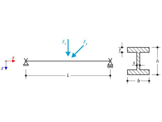
La structure est composée d'une poutre profilée en I et de deux poutres treillis tubulaires. La structure contient plusieurs imperfections et est chargée par la force Fz. Le poids propre est négligé dans cet exemple. Déterminez les flèches uy et uz ainsi que la rotation axiale φx au point de fin (point 4). L'exemple de vérification est basé sur l'exemple introduit par Gensichen et Lumpe.
Une poutre continue avec quatre travées est chargée par les efforts normaux et les efforts de flexion (placeant ainsi les imperfections). Tous les appuis sont à fourche - le gauchissement est libre. Déterminer les déplacements uy etuz, les moments My, Mz, Mω et MTpri ainsi que la rotation φx. L'exemple de vérification est basé sur l'exemple introduit par Gensichen et Lumpe.
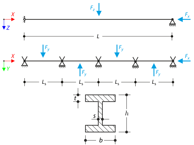
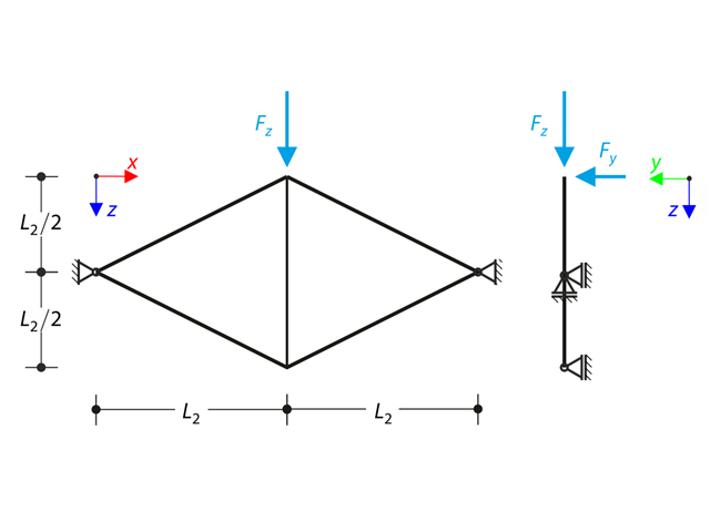
La rotation axiale du profilé en I est limitée aux deux extrémités à l'aide des appuis à fourche (le gauchissement n'est pas limité). La structure est chargée par deux forces transversales en son centre. Le poids propre est négligé dans cet exemple. Déterminer les flèches maximales de la structure uy,max et uz,max, la rotation maximale φx,max, les moments fléchissants maximaux My,max et Mz,max et les moments de torsion maximaux MT,max, MTpri,max MTsec,max et Mω,max. L'exemple de vérification est basé sur l'exemple introduit par Gensichen et Lumpe.
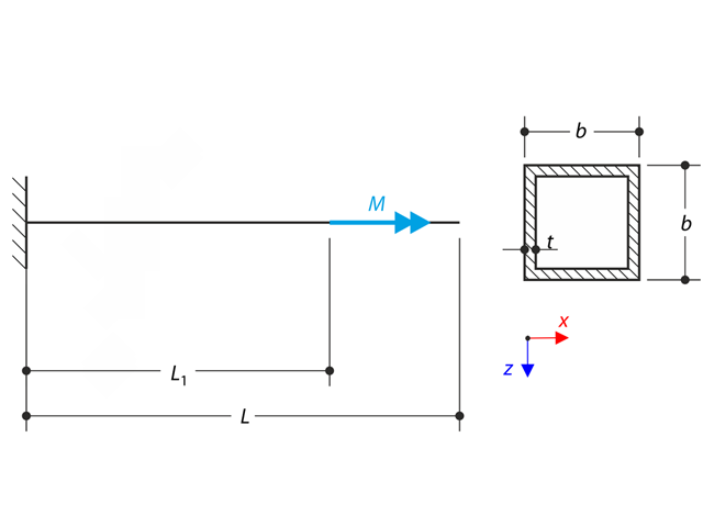
Un porte-à-faux à parois minces d'un profilé QRO est entièrement fixé à l'extrémité gauche et le gauchissement est libre. Le porte-à-faux est soumis à un moment de rotation. Les petites déformations sont considérées et le poids propre est négligé. Déterminez la rotation maximale, le moment primaire, le moment secondaire et le moment de gauchissement. L'exemple de vérification est basé sur l'exemple introduit par Gensichen et Lumpe.
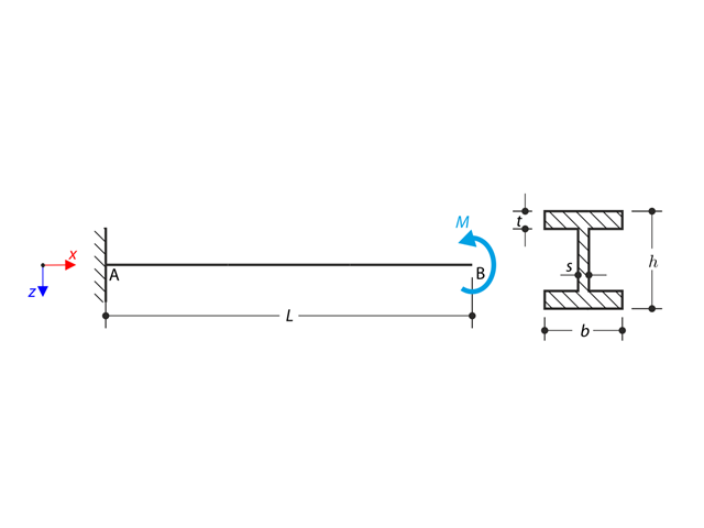
Un porte-à-faux de profilé en I est supporté à l'extrémité gauche et est chargé par le moment de rotation M. Le but de cet exemple est de comparer l'appui encastré avec l'appui latéral et torsionnel et d'analyser le comportement de certaines valeurs représentatives. La comparaison avec la solution à l'aide de plaques est également effectuée. L'exemple de vérification est basé sur l'exemple introduit par Gensichen et Lumpe.
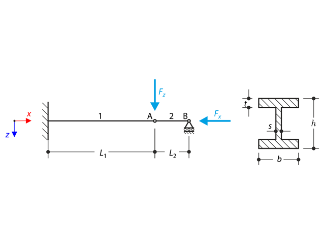
Une structure en profilé en I est entièrement encastrée à l'extrémité gauche et intégrée dans un support glissant à l'extrémité droite. La structure est composée de deux segments. Le poids propre est négligé dans cet exemple. Déterminer la flèche maximale de la structure uz,max, le moment fléchissant My sur l'extrémité fixe, la rotation &svarphi;2,y du segment 2 et la force de réaction RBz à l'aide de l'analyse géométriquement linéaire et de l'analyse du second ordre. L'exemple de vérification est basé sur l'exemple introduit par Gensichen et Lumpe.
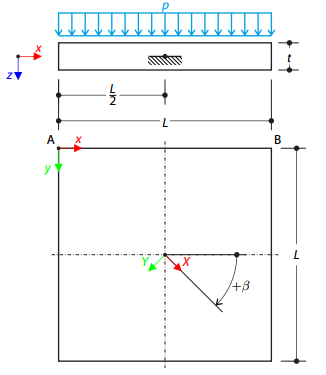
Une plaque orthotrope carrée en couches est complètement encastrée en son point central et soumise à la pression. Comparons les flèches des coins de plaque pour vérifier l'exactitude de la transformation.
Une structure faite de profilé en I est intégrée dans les appuis des fourches. The axial rotation is restricted on both ends while warping is enabled. The structure is loaded by two transverse forces in the middle. The verification example is based on the example introduced by Gensichen and Lumpe.
Un treillis plan composé de quatre barres inclinées et d'une barre verticale est chargé au niveau du nœud supérieur à l'aide d'une force verticale et d'une force hors du plan. Assuming the large deformation analysis and neglecting the self-weight, determine the normal forces of the members and the out-of-plane displacement of the upper node.
A symmetrical shallow structure is made of eight equal truss members, which are embedded into hinge supports. The structure is loaded by a concentrated force and alternatively by imposed nodal deformation over the critical limit point when the snap-through occurs. Imposed nodal deformation is used in RFEM 5 and RSTAB 8 to obtain the full equilibrium path of the snap-through. Le poids propre est négligé dans cet exemple. Determine the relationship between the actual loading force and the deflection, considering large deformation analysis. Evaluate the load factor at the given deflections.
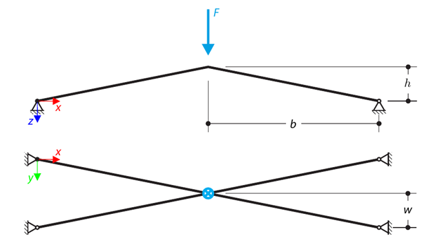
A structure is made of four truss members, which are embedded into hinge supports. The structure is loaded by a concentrated force and alternatively by imposed nodal deformation over the critical limit point, when snap-through occurs. Imposed nodal deformation is used in RFEM 5 and RSTAB 8 to obtain the full equilibrium path of the snap-through. Le poids propre est négligé dans cet exemple. Determine the relationship between the actual loading force and the deflection, considering large deformation analysis. Evaluate the load factor at given deflections.
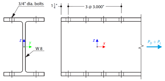
Une barre en forme de W selon la norme ASTM A992 est sélectionnée pour supporter une charge permanente de 30 000 kips et une charge d'exploitation de 90 000 kips en traction. Verify the member strength using both LRFD and ASD.
Considérons la travée de barre ASTM A992 W 18×50 ainsi que les poids propre et les charges d'exploitation représentés sur la Figure 1. The member is limited to a maximum nominal depth of 18 inches. The live load deflection is limited to L/360. The beam is simply supported and continuously braced. Verify the available flexural strength of the selected beam, based on LRFD and ASD.
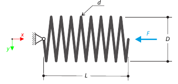
Une force de compression s'exerce sur un ressort hélicoïdal fortement hélicoïdal. The spring has middle diameter D, wire diameter d, and it consists of i turns. The total length of the spring is L. Determine the total deflection of the spring for the member model and one‑turn deflection for the solid model.
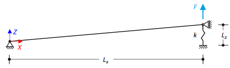
Une barre légèrement inclinée est chargée par une force concentrée, maintenue par un ressort à une extrémité et supportée à l'autre extrémité. Assuming large deformations and neglecting the member's self-weight, determine its maximum upward deflection.
A structure made of an I-profile is fully fixed on the left end and embedded into the sliding support on the right end. The structure consists of two segments. Le poids propre est négligé dans cet exemple. Determine the maximum deflection of the structure, the bending moment on the fixed end, the rotation of segment 2, and the reaction force at point B by means of the geometrically linear analysis and the second-order analysis. The verification example is based on the example introduced by Gensichen and Lumpe.
Un porte-à-faux à parois minces d'un profilé QRO est entièrement fixé à l'extrémité gauche et le gauchissement est activé. The cantilever is subjected to torque. Small deformations are considered, and the self-weight is neglected. Determine the maximum rotation, primary moment, secondary moment, and warping moment. The verification example is based on the example introduced by Gensichen and Lumpe.
Un porte-à-faux profilé en I est supporté à l'extrémité gauche et chargé par un couple. The aim of this example is to compare the fixed support with the fork support and to investigate the behavior of some representative quantities. Comparison is also made to the solution by means of plates. Small deformations are considered, and the self-weight is neglected. Determine the rotation in the midpoint of the cantilever, and in case of the member entity with warping, determine the values of the primary torsional moment, the secondary torsional moment, and the warping moment both on the left end (point A) and the right end (point B).