4 Model Data
- 4.1 Nodes
- 4.2 Lines
- 4.3 Materials
- 4.4 Surfaces
- 4.5 Solids
- 4.6 Openings
- 4.7 Nodal Supports
- 4.8 Line Supports
- 4.9 Surface Supports
- 4.10 Line Hinges
- 4.11 Variable Thicknesses
- 4.12 Orthotropic Surfaces and Membranes
- 4.13 Cross-Sections
- 4.14 Member Hinges
- 4.15 Member Eccentricities
- 4.16 Member Divisions
- 4.17 Members
- 4.18 Ribs
- 4.19 Member Elastic Foundations
- 4.20 Member Nonlinearities
- 4.21 Sets of Members
- 4.22 Intersections
- 4.23 FE Mesh Refinements
- 4.24 Nodal Releases
- 4.25 Line Release Types
- 4.26 Line Releases
- 4.27 Surface Release Types
- 4.28 Surface Releases
- 4.29 Connection of Two Members
- 4.30 Joints
- 4.31 Nodal Constraints
6 Loads
- 6.1 Nodal Loads
- 6.2 Member Loads
- 6.3 Line Loads
- 6.4 Surface Loads
- 6.5 Solid Loads
- 6.6 Free Concentrated Loads
- 6.7 Free Line Loads
- 6.8 Free Rectangular Loads
- 6.9 Free Circular Loads
- 6.10 Free Polygon Loads
- 6.11 Free Variable Loads
- 6.12 Imposed Nodal Deformations
- 6.13 Imposed Line Displacements
- 6.14 Imperfections
- 6.15 Generated Loads
8 Results
- 8.1 Nodes - Support Forces
- 8.2 Nodes - Deformations
- 8.3 Lines - Support Forces
- 8.4 Members - Local Deformations
- 8.5 Members - Global Deformations
- 8.6 Members - Internal Forces
- 8.7 Members - Contact Forces
- 8.8 Members - Strains
- 8.9 Members - Coefficients for Buckling
- 8.10 Member Slendernesses
- 8.11 Sets of Members - Internal Forces
- 8.12 Cross-Sections - Internal Forces
- 8.13 Surfaces - Local Deformations
- 8.14 Surfaces - Global Deformations
- 8.15 Surfaces - Basic Internal Forces
- 8.16 Surfaces - Principal Internal Forces
- 8.17 Surfaces - Design Internal Forces
- 8.18 Surfaces - Basic Stresses
- 8.19 Surfaces - Principal Stresses
- 8.20 Surfaces - Other Stresses
- 8.21 Surfaces - Contact Stresses
- 8.22 Surfaces - Equivalent Stresses - von Mises
- 8.23 Surfaces - Equivalent Stresses - Tresca
- 8.24 Surfaces - Equivalent Stresses - Rankine
- 8.25 Surfaces - Equivalent Stresses - Bach
- 8.26 Surfaces - Basic Strains
- 8.27 Surfaces - Principal Strains
- 8.28 Surfaces - Maximum Strains
- 8.29 Surfaces - Strains - von Mises
- 8.30 Surfaces - Strains - Tresca
- 8.31 Surfaces - Strains - Rankine
- 8.32 Surfaces - Strains - Bach
- 8.33 Solids - Deformations
- 8.34 Solids - Stresses
- 8.35 Solids - Strains
- 8.36 Solids - Gas Pressure
10 Printout
-
10.1 Printout Report
- 10.1.1 Creating or Opening Printout Reports
- 10.1.2 Working in the Printout Report
- 10.1.4 Adjusting Printout Report Headers
- 10.1.5 Inserting RFEM Graphics
- 10.1.6 Inserting Graphics and Texts
- 10.1.7 Printout Report Template
- 10.1.8 Adjusting Layouts
- 10.1.9 Creating Cover Sheets
- 10.1.10 Printing a Printout Report
- 10.1.11 Exporting a Printout Report
- 10.1.12 Language Settings
11 Program Functions
-
11.4 Editing Objects
- 11.4.1 Move and Copy
- 11.4.2 Rotate
- 11.4.3 Mirror
- 11.4.4 Project
- 11.4.5 Scale
- 11.4.6 Shear
- 11.4.7 Dividing Lines and Members
- 11.4.8 Connecting Lines and Members
- 11.4.9 Merging Lines and Members
- 11.4.10 Extending Lines and Members
- 11.4.11 Joining Members
- 11.4.12 Inserting Nodes
- 11.4.13 Inserting Members
- 11.4.14 Assigning Member Properties Graphically
- 11.4.15 Rounding Corners
- 11.4.16 Splitting Surfaces
- 11.4.17 Applying Tangents to Circles
- 11.4.18 Changing the Numbering
检索结果
“Interface utilisateur”的3个结果
12.5 Interfaces
/zh/downloads-and-information/documents/online-manuals/rfem-5/004480
3 User Interface
/zh/downloads-and-information/documents/online-manuals/rfem-5/004185
3.4 RFEM User Interface
/zh/downloads-and-information/documents/online-manuals/rfem-5/004189
长度: 00:00:21 min
长度: 00:01:00 min
长度: 00:00:47 min

长度: 00:02:14 min
长度: 00:00:20 min

长度: 00:00:13 min
长度: 00:00:30 min
长度: 00:00:39 min
长度: 00:00:10 min


本文阐述并解释了索的抗弯刚度对其内力的影响。 本文还介绍了如何减少这种影响的方法。
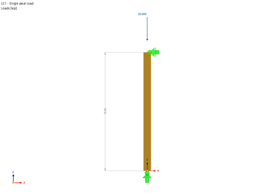
使用“木结构设计”模块,可以按照 2018 NDS 标准 ASD 方法进行木柱设计。 准确计算木杆件的抗压承载力和调整系数对于安全考虑和设计非常重要。 下面的文章将按照 NDS 2018 标准,使用逐步的解析方程验证“木结构设计”模块计算的最大临界屈曲强度,包括受压调整系数、调整后的抗压设计值和最终设计比率。
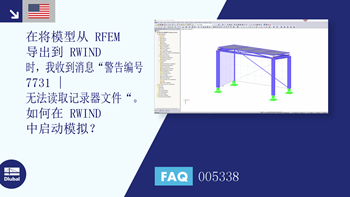
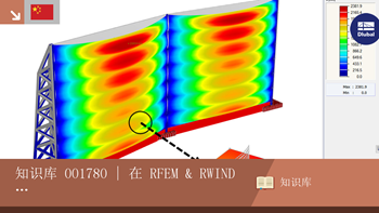
RWIND 2 是一款专门针对建筑风工程的 CFD 软件。 可以对任何建筑物周围的风流进行数值模拟,包括不规则的或特殊的几何形状,以确定建筑表面和杆件上的风荷载。 RWIND 2可以与RFEM/RSTAB集成用于结构分析和设计,也可以作为独立的应用程序使用。
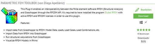
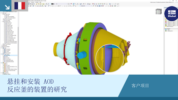
本文介绍了参数化有限元工具箱的开发以及使用这个新工具的一些可用工作流程。


.JPG?mw=350&hash=d57486d45e0440dd9a6be9be91368a3e4f42f4b9)
.JPG?mw=350&hash=df48834f2d658081d5f412d698c4da41b73309b9)


实体应力的结果可以在有限元中显示为彩色的三维点。
.png?mw=512&hash=ea9bf0ab53a4fb0da5c4ed81d32d53360ab2820c)
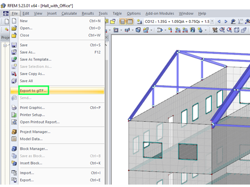
RFEM 中节点自由度数目不再是全局计算参数( 3D 模型中每个网格节点 6 个自由度,在翘曲扭转分析中为 7 个自由度)。 每个节点通常被认为有不同数量的自由度,从而在计算中导致方程的数目是可变的。
这种修改可以提高计算速度,特别是对于可以显著简化结构体系的模型(例如桁架和膜结构)。
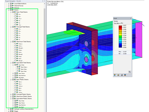
在 RFEM 中的结果导航器和表 4.0 中可以显示杆件、面和实体的扩展应变(例如重要的主应变、等效总应变等)。
例如,在进行面单元连接的塑性设计时显示主要的塑性应变。


.jpg?mw=350&hash=8f312d6c75a747d88bf9d0f5b1038595900b96c1)
