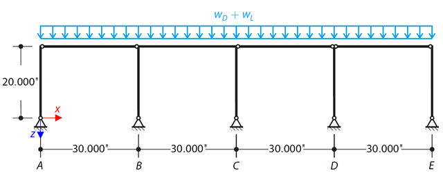
Determine the required strengths and effective length factors for the ASTM A992 material columns in the moment frame shown in Figure 1 for the maximum gravity load combination, using LRFD and ASD.

An ASTM A992 W-shaped member is selected to carry a dead load of 30.000 kips and a live load of 90.000 kips in tension. Verify the member strength using both LRFD and ASD.

Consider an ASTM A992 W 18x50 beam forspan and uniform dead and live loads as shown in Figure 1. The member is limited to a maximum nominal depth of 18 inches. The live load deflection is limited to L/360. The beam is simply supported and continuously braced. Verify the available flexural strength of the selected beam, based on LRFD and ASD.

An ASTM A992 W 24×62 beam with end shears of 48.000 and 145.000 kips from the dead and live loads, respectively, is shown in Figure 1. Verify the available shear strength of the selected beam, based on LRFD and ASD.

Using AISC Manual tables, determine the available compressive and flexural strengths and whether the ASTM A992 W14x99 beam has sufficient available strength to support the axial forces and moments shown in Figure 1, obtained from a second-order analysis that includes P-𝛿 effects.
Determine the allowable axial compressive strength of a pinned 8-foot-long beam of various cross-sections made of Alloy 6061-T6 and laterally restrained to prevent buckling about its weak axis in accordance with the 2020 Aluminum Design Manual.
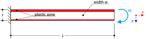
A cantilever is fully fixed on the left end and loaded by a bending moment on the right end. The material has different plastic strengths under tension and compression.
Determine the allowable axial compressive strength of a pinned 8-foot-long beam of various cross-sections made of Alloy 6061-T6 and laterally restrained to prevent buckling about its weak axis in accordance with the 2020 Aluminum Design Manual.
Determine the allowable axial compressive strength of a pinned 8-foot-long beam of various cross-sections made of Alloy 6061-T6 and laterally restrained to prevent buckling about its weak axis in accordance with the 2015 Aluminum Design Manual.
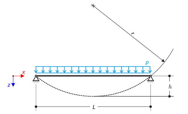
A cable is loaded by means of a uniform load. This causes the deformed shape in the form of the circular segment. Determine the equilibrium force of the cable to obtain the given sag of the cable. The add-on module RF-FORM-FINDING is used for this purpose. Elastic deformations are neglected both in RF-FORM-FINDING and in the analytical solution; self-weight is also neglected in this example.
Determine the required strengths and effective length factors for the ASTM A992 material columns in the moment frame shown in Figure 1 for the maximum gravity load combination, using LRFD and ASD.
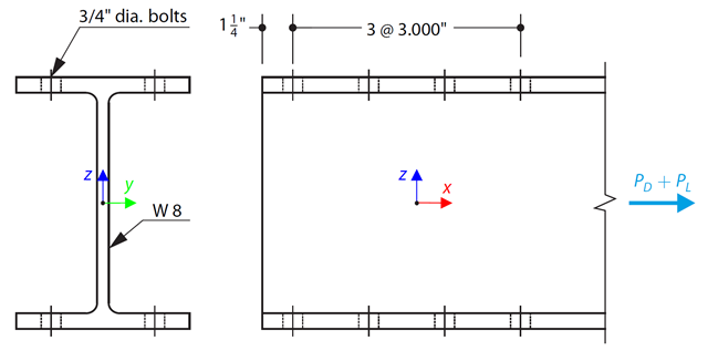
An ASTM A992 W-shaped member is selected to carry a dead load of 30.000 kips and a live load of 90.000 kips in tension. Verify the member strength using both LRFD and ASD.
Consider an ASTM A992 W 18×50 beam forspan and uniform dead and live loads as shown in Figure 1. The member is limited to a maximum nominal depth of 18 inches. The live load deflection is limited to L/360. The beam is simply supported and continuously braced. Verify the available flexural strength of the selected beam, based on LRFD and ASD.
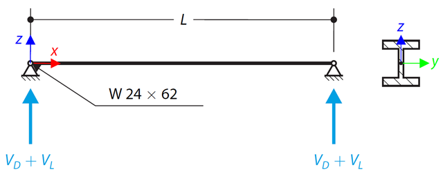
An ASTM A992 W 24×62 beam with end shears of 48.000 and 145.000 kips from the dead and live loads, respectively, is shown in Figure 1. Verify the available shear strength of the selected beam, based on LRFD and ASD.
Using AISC Manual tables, determine the available compressive and flexural strengths and whether the ASTM A992 W14x99 beam has sufficient available strength to support the axial forces and moments shown in Figure 1, obtained from a second-order analysis that includes P-𝛿 effects.
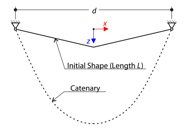
A very stiff cable is suspended between two supports. Determine the equilibrium shape of the cable (the catenary), consider the gravitational acceleration, and neglect the stiffness of the cable. Verify the position of the cable at the given test points.
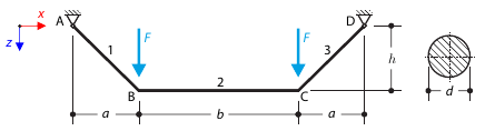
A cable in the initial position is loaded by two concentrated forces. The self‑weight is neglected. Determine the normal forces in the cable.
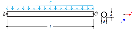
A steel cable or membrane with pins on both ends is loaded by distributed loading. Neglecting its self-weight, determine the maximum deflection of the structure using the large deformation analysis.
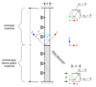
Determine the maximum deflection of a three-dimensional block fixed at both ends. The block is divided in the middle: the upper half is made of an elastic material and the lower part is made of timber - an elasto-plastic othotropic material with the yield surface described according to the Tsai-Wu plasticity theory. The block's middle plane is subjected to vertical pressure.
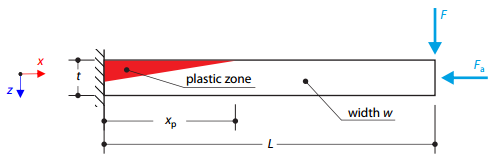
A cantilever is fully fixed on the left end and loaded by a transverse force and an axial force on the right end. The tensile strength is zero and the behavior in the compression remains elastic.